Monthly Archives: July 2017

iBGP PE-CE

Different RD values for different sites – mandatory.

neighbor <address> internal-vpn-client
neighbor <address> route-reflector-clinet
neighbor <address> next-hop-self

NHS – mandatory.

ATTR_SET – new BGP attribute, which “embeds” CE BGP attributes. CE attributes are transparent for VPN backbone. VPN backbone attributes are not passed to CE.

The ATTR_SET attribute has this format:

 
                      +------------------------------+
                      | Attr Flags (O|T) Code = 128  |
                      +------------------------------+
                      | Attr. Length (1 or 2 octets) |
                      +------------------------------+
                      | Origin AS (4 octets)         |
                      +------------------------------+
                      | Path Attributes (variable)   |
                      +------------------------------+

The attribute flags are the regular BGP attribute flags (refer to RFC 4271). The attribute length indicates whether the attribute length is one or two octets. The purpose of the Origin AS field is to prevent the leak of one route originated in one AS to be leaked to another AS without the proper manipulation of the AS_PATH. The variable length Path Attributes field carries the VPN BGP attributes that must be carried across the SP core.

When PE1 receives the BGP prefix 10.100.1.1/32 from CE1, it stores it twice:

PE1#show bgp vpnv4 unicast all 10.100.1.1/32
BGP routing table entry for 65000:1:10.100.1.1/32, version 21
Paths: (2 available, best #1, table customer1)
  Advertised to update-groups:
     5         
  Refresh Epoch 1
  Local, (Received from ibgp-pece RR-client)
    10.1.1.4 (via vrf customer1) from 10.1.1.4 (10.100.1.1)
      Origin IGP, metric 0, localpref 200, valid, internal, best
      mpls labels in/out 18/nolabel
      rx pathid: 0, tx pathid: 0x0
  Refresh Epoch 1
  Local, (Received from ibgp-pece RR-client), (ibgp sourced)
    10.1.1.4 (via vrf customer1) from 10.1.1.4 (10.100.1.1)
      Origin IGP, localpref 100, valid, internal
      Extended Community: RT:1:1
      mpls labels in/out 18/nolabel
      rx pathid: 0, tx pathid: 0

The first path is the actual path on PE1, because it is received from CE1.

The second path is the path that is advertised towards the RRs/PE routers. It is marked with ibgp sourced. It contains the ATTR_SET attribute. Notice that this path has one or more Route Targets (RTs) attached to it.

PE1 advertises the prefix as shown here:

PE1#show bgp vpnv4 unicast all neighbors 192.168.100.3 advertised-routes 
BGP table version is 7, local router ID is 192.168.100.1
Status codes: s suppressed, d damped, h history, * valid, > best, i - internal, 
              r RIB-failure, S Stale, m multipath, b backup-path, f RT-Filter, 
              x best-external, a additional-path, c RIB-compressed, 
Origin codes: i - IGP, e - EGP, ? - incomplete
RPKI validation codes: V valid, I invalid, N Not found

     Network          Next Hop            Metric LocPrf Weight Path
Route Distinguisher: 65000:1 (default for vrf customer1)
 *>i 10.100.1.1/32    10.1.1.4                 0    200      0 i

Total number of prefixes 1

This is how the RR sees the path:

RR#show bgp vpnv4 un all 10.100.1.1/32
BGP routing table entry for 65000:1:10.100.1.1/32, version 10
Paths: (1 available, best #1, no table)
  Advertised to update-groups:
     3         
  Refresh Epoch 1
  Local, (Received from a RR-client)
    192.168.100.1 (metric 11) (via default) from 192.168.100.1 (192.168.100.1)
      Origin IGP, localpref 100, valid, internal, best
      Extended Community: RT:1:1
      Originator: 10.100.1.1, Cluster list: 192.168.100.1
      ATTR_SET Attribute: 
        Originator AS 65000
        Origin IGP
        Aspath 
        Med 0
        LocalPref 200
        Cluster list 
        192.168.100.1, 
        Originator 10.100.1.1
      mpls labels in/out nolabel/18
      rx pathid: 0, tx pathid: 0x0

Notice that the local preference of this VPNv4 unicast prefix in the core is 100. In the ATTR_SET, the original local preference of 200 is stored. However, this is transparent to the RR in the SP core.

On PE2, you see the prefix as shown here:

PE2#show bgp vpnv4 unicast all 10.100.1.1/32
BGP routing table entry for 65000:1:10.100.1.1/32, version 5
Paths: (1 available, best #1, no table)
  Not advertised to any peer
  Refresh Epoch 2
  Local
    192.168.100.1 (metric 21) (via default) from 192.168.100.3 (192.168.100.3)
      Origin IGP, localpref 100, valid, internal, best
      Extended Community: RT:1:1
      Originator: 10.100.1.1, Cluster list: 192.168.100.3, 192.168.100.1
      ATTR_SET Attribute: 
        Originator AS 65000
        Origin IGP
        Aspath 
        Med 0
        LocalPref 200
        Cluster list 
        192.168.100.1, 
        Originator 10.100.1.1
      mpls labels in/out nolabel/18
      rx pathid: 0, tx pathid: 0x0
BGP routing table entry for 65000:2:10.100.1.1/32, version 6
Paths: (1 available, best #1, table customer1)
  Advertised to update-groups:
     1         
  Refresh Epoch 2
  Local, imported path from 65000:1:10.100.1.1/32 (global)
    192.168.100.1 (metric 21) (via default) from 192.168.100.3 (192.168.100.3)
      Origin IGP, metric 0, localpref 200, valid, internal, best
      Originator AS(ibgp-pece): 65000
      Originator: 10.100.1.1, Cluster list: 192.168.100.1
      mpls labels in/out nolabel/18
      rx pathid:0, tx pathid: 0x0

The first path is the one received from the RR, with the ATTR_SET. Note that the RD is 65000:1, the origin RD. The second path is the imported path from the VRF table with RD 65000:1. The ATTR_SET has been removed.

This is the path as seen on CE2:

CE2#show bgp ipv4 unicast 10.100.1.1/32
BGP routing table entry for 10.100.1.1/32, version 10
Paths: (1 available, best #1, table default)
  Not advertised to any peer
  Refresh Epoch 1
  Local
    10.1.2.2 from 10.1.2.2 (192.168.100.2)
      Origin IGP, metric 0, localpref 200, valid, internal, best
      Originator: 10.100.1.1, Cluster list: 192.168.100.2, 192.168.100.1
      rx pathid: 0, tx pathid: 0x0

Notice that the next-hop is 10.1.2.2, which is PE2. The cluster list contains routers PE1 and PE2. These are the RRs that matter inside the VPN. The SP RR (10.100.1.3) is not in the cluster list.

The local preference of 200 has been preserved inside the VPN across the SP network.
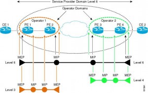
 

Y.1731 CFM & PM

CFM

ME Maintenance Entity
MEG ME Group
MEL MEG Level
MEP MEG End Point
MIP MEG Intermediate Point

Eight MEG Levels are available to accommodate different network deployment scenarios:
• Customer role is assigned three MEG Levels: 7, 6, and 5.
• Provider role is assigned two MEG Levels: 4 and 3.
• Operator role is assigned three MEG Levels: 2, 1, and 0.

Transmission periods:
• 3.33 ms: Default transmission period for protection switching application (transmission rate of 300 frames/second).
• 10 ms: (Transmission rate is 100 frames/second).
• 100 ms: Default transmission period for performance monitoring application (transmission rate of 10 frames/second).
• 1 s: Default transmission period for fault management application (transmission rate of 1 frame/second).
• 10 s: (Transmission rate of 6 frames/minute).
• 1 min: (Transmission rate of 1 frame/minute).
• 10 min: (Transmission rate of 6 frames/hour).

Fault management
CCM Continuity Check Message
If no CCM frames from a peer MEP are received within the interval equal to 3.5 times the
receiving MEP’s CCM transmission period, loss of continuity with peer MEP is detected.

Ethernet Loopback function (ETH-LB) is used to verify connectivity of a MEP with a MIP or peer
MEP(s).
LBM LoopBack Message
LBR LoopBack Reply
LBR frame within 5 seconds.
Transaction ID from the same MEP may be repeated within one minute.
Unicast ETH-LB:
• To verify bidirectional connectivity of a MEP with a MIP or a peer MEP.
• To perform a bidirectional in-service or out-of-service diagnostics test between a pair of
peer MEPs. This includes verifying bandwidth throughput, detecting bit errors, etc.
The MIP or peer MEP is identified by its MAC address. This MAC address is encoded in the DA of the Unicast request frame. Transmitted only by MEP on the on-demand basis.
Multicast ETH-LB:
Multicast ETH-LB function is used to verify bidirectional connectivity of a MEP with its peer
MEPs. When Multicast-LB is invoked on a MEP, a Multicast frame with ETH-LB request information is sent from a MEP to other peer MEPs in the same MEG.  A MIP is transparent to the Multicast frames with ETH-LB request information.

Ethernet Link Trace function (ETH-LT)
• Adjacent Relation Retrieval – ETH-LT function can be used to retrieve adjacency
relationship between a MEP and a remote MEP or MIP. The result of running ETH-LT
function is a sequence of MIPs from the source MEP until the target MIP or MEP. Each
MIP and/or MEP is identified by its MAC address.
• Fault Localization – ETH-LT function can be used for fault localization. When a fault (e.g.,
a link and/or a device failure) or a forwarding plane loop occurs, the sequence of MIPs
and/or MEP will likely be different from the expected one. Difference in the sequences
provides information about the fault location.
LTM Link Trace Message
LTR Link Trace Reply
LTR frames within 5 seconds.
Transaction ID from the same MEP may be repeated within one minute.
If the TTL field value is 0, the LTM frame is discarded.
Only LTM frames with the same MEG Level
As each network element, containing the MIPs or MEP, needs to be aware of the TargetMAC
address in the received LTM frame and associates it to a single egress port, in order for the MIP or MEP to reply, a Unicast ETH-LB to the TargetMAC address could be performed by a MEP before transmitting the LTM frame.

Ethernet Alarm Indication Signal function (ETH-AIS)
Suppress alarms following detection of defect conditions at the server (sub) layer. ETH-AIS is not expected to be applied in the STP environments.

Ethernet Remote Defect Indication function (ETH-RDI) can be used by a MEP to communicate to
its peer MEPs that a defect condition has been encountered.

Ethernet Locked Signal function (ETH-LCK) is used to communicate the administrative locking of a server (sub) layer MEP and consequential interruption of data traffic forwarding towards the MEP expecting this traffic. It allows a MEP receiving frames with ETH-LCK information to differentiate between a defect condition and an administrative locking action at the server (sub) layer MEP. An example of an application that would require administrative locking of a MEP is the out-of-service ETH-Test.

Ethernet Test Signal function (ETH-Test) is used to perform one-way on-demand in-service or outof-service diagnostics tests. This includes verifying bandwidth throughput, frame loss, bit
errors, etc.
Different Sequence Number must be used for every TST frame, no Sequence Number from the
same MEP may be repeated within one minute.

Ethernet Automatic Protection Switching function (ETH-APS) is used to control protection
switching operations to enhance reliability.

Ethernet Maintenance Communication Channel function (ETH-MCC) provides a maintenance
communication channel between a pair of MEPs. ETH-MCC can be used to perform remote
management.
A remote MEP, upon receiving a frame with ETH-MCC information and with a correct MEG
Level, passes the ETH-MCC information to the management agent which may additionally respond.

Ethernet Experimental OAM (ETH-EXP) is used for the experimental OAM functionality which can be used within an administrative domain on a temporary basis. Interoperability of the experimental OAM functionality is not expected across different administrative domains.

Ethernet Vendor Specific OAM (ETH-VSP) is used for vendor-specific OAM functionality which may be used by a vendor across its equipment. Interoperability of vendor-specific OAM functionality is not expected across different vendors’ equipment.

Performance monitoring
Frame Loss Measurement
(ETH-LM)

Frame Delay Measurement (ETH-DM)

Throughput measurement