NSF, NSR, GR

Non-Stop Forwarding (NSF): The ability of the forwarding plane to continue running “headless” if the control plane stops. NSF allows you to switch from a primary to a backup control plane without disrupting forwarding.

The objective of NSR is to prevent, or at least minimize, the effect of broken peering sessions. A  newer generation of NSR uses internal processes to keep the backup control plane aware of routing protocol state and adjacency maintenance activities, so that after a switchover the backup control plane can take charge of the existing peering sessions rather than having to establish new ones. NSR process is internal (and vendor specific) there is no need for the neighbors to support any kind of protocol extension.

Graceful Restart (GR) protocol extensions.


OSPF RFC1583 vs RFC2328 compatibility

Best path selection:
RFC1583 – best path based solely on cost.
RFC2328 – Intra-area paths that use non-backbone areas are always the most preferred.

Can lead to the loops:
https://www.cisco.com/c/en/us/support/docs/ip/open-shortest-path-first-ospf/117824-config-ospf-00.html

Summary metric:
RFC1583 – lowest metric of the componet routes
RFC2328 – highest metric of the components.

OSPF RFC1587 vs RFC3101 NSSA compatibility.

  1. Path selection
    1587:
    a. Any type 5 LSA.
    b. A type-7 LSA with the P-bit set and the forwarding
    address non-zero.
    c. Any other type-7 LSA
    RFC3101:
    1. A Type-7 LSA with the P-bit set.
    2. A Type-5 LSA.
    3. The LSA with the higher router ID.
  2. The P-bit default is now defined as cleared.
  3. A new area configuration parameter, NSSATranslatorRole, is defined in Appendix D. It specifies whether or not an NSSA router will unconditionally translate Type-7 LSAs to Type-5 LSAs when acting as an NSSA border router.

Router Virtualization Concepts; IOS XR Virtualization

Hardware-Isolated Virtual Router (HVR)

Dedicates both control plane and data plane resources on a per-module boundary to individual virtual entities.

HVR implementation multiplies the available resources (add modules, processors, etc.).
Software-Isolated Virtual Router (SVR)
Share hardware ressources in the data plane.
Multiple guest operating systems to overlay on a host operating system – detrimental impact on scale because it introduces significant contention of resources.
Approach to overprovision ressources on all SVRs – wastes ressources decreasing overall scale.

Integrate virtualization into kernel. Same contention of resources. Complexity and instability in the kernel.

Virtualization in the individual applications. Better scale. Complicates design, testing and management.

SVR implementation divides the available resources.

Chassis resources (power supplies, blowers, fabric) are shared for both HVR and SVR.

Secure Domain Routers
HVR technology.
Distributed Route Processors (DRPs; hardware modules)  = full isolation between instances.
SDR defined on per-slot boundary with entire RP and Modular Service Card dedicated to an SDR.

The only parts of the chassis that are shared are the fabric, the fans, and the power supplies.
Owner SDR -system-wide functions including creation of non-owner SDRs. Admin config mode access.

In each SDR, administration and control capabilities are provided by the designated secure  domain router system controller (DSDRSC). Each SDR must include a DSDRSC to operate, and you must assign an RP or DRP to act as the DSDRSC.

The DSDRSC of the owner SDR is also the DSC of the entire system.
CPU and memory of an SDR are not shared with other SDRs

iBGP PE-CE

Different RD values for different sites – mandatory.

neighbor <address> internal-vpn-client
neighbor <address> route-reflector-clinet
neighbor <address> next-hop-self

NHS – mandatory.

ATTR_SET – new BGP attribute, which “embeds” CE BGP attributes. CE attributes are transparent for VPN backbone. VPN backbone attributes are not passed to CE.

The ATTR_SET attribute has this format:

 
                      +------------------------------+
                      | Attr Flags (O|T) Code = 128  |
                      +------------------------------+
                      | Attr. Length (1 or 2 octets) |
                      +------------------------------+
                      | Origin AS (4 octets)         |
                      +------------------------------+
                      | Path Attributes (variable)   |
                      +------------------------------+

The attribute flags are the regular BGP attribute flags (refer to RFC 4271). The attribute length indicates whether the attribute length is one or two octets. The purpose of the Origin AS field is to prevent the leak of one route originated in one AS to be leaked to another AS without the proper manipulation of the AS_PATH. The variable length Path Attributes field carries the VPN BGP attributes that must be carried across the SP core.

When PE1 receives the BGP prefix 10.100.1.1/32 from CE1, it stores it twice:

PE1#show bgp vpnv4 unicast all 10.100.1.1/32
BGP routing table entry for 65000:1:10.100.1.1/32, version 21
Paths: (2 available, best #1, table customer1)
  Advertised to update-groups:
     5         
  Refresh Epoch 1
  Local, (Received from ibgp-pece RR-client)
    10.1.1.4 (via vrf customer1) from 10.1.1.4 (10.100.1.1)
      Origin IGP, metric 0, localpref 200, valid, internal, best
      mpls labels in/out 18/nolabel
      rx pathid: 0, tx pathid: 0x0
  Refresh Epoch 1
  Local, (Received from ibgp-pece RR-client), (ibgp sourced)
    10.1.1.4 (via vrf customer1) from 10.1.1.4 (10.100.1.1)
      Origin IGP, localpref 100, valid, internal
      Extended Community: RT:1:1
      mpls labels in/out 18/nolabel
      rx pathid: 0, tx pathid: 0

The first path is the actual path on PE1, because it is received from CE1.

The second path is the path that is advertised towards the RRs/PE routers. It is marked with ibgp sourced. It contains the ATTR_SET attribute. Notice that this path has one or more Route Targets (RTs) attached to it.

PE1 advertises the prefix as shown here:

PE1#show bgp vpnv4 unicast all neighbors 192.168.100.3 advertised-routes 
BGP table version is 7, local router ID is 192.168.100.1
Status codes: s suppressed, d damped, h history, * valid, > best, i - internal, 
              r RIB-failure, S Stale, m multipath, b backup-path, f RT-Filter, 
              x best-external, a additional-path, c RIB-compressed, 
Origin codes: i - IGP, e - EGP, ? - incomplete
RPKI validation codes: V valid, I invalid, N Not found

     Network          Next Hop            Metric LocPrf Weight Path
Route Distinguisher: 65000:1 (default for vrf customer1)
 *>i 10.100.1.1/32    10.1.1.4                 0    200      0 i

Total number of prefixes 1

This is how the RR sees the path:

RR#show bgp vpnv4 un all 10.100.1.1/32
BGP routing table entry for 65000:1:10.100.1.1/32, version 10
Paths: (1 available, best #1, no table)
  Advertised to update-groups:
     3         
  Refresh Epoch 1
  Local, (Received from a RR-client)
    192.168.100.1 (metric 11) (via default) from 192.168.100.1 (192.168.100.1)
      Origin IGP, localpref 100, valid, internal, best
      Extended Community: RT:1:1
      Originator: 10.100.1.1, Cluster list: 192.168.100.1
      ATTR_SET Attribute: 
        Originator AS 65000
        Origin IGP
        Aspath 
        Med 0
        LocalPref 200
        Cluster list 
        192.168.100.1, 
        Originator 10.100.1.1
      mpls labels in/out nolabel/18
      rx pathid: 0, tx pathid: 0x0

Notice that the local preference of this VPNv4 unicast prefix in the core is 100. In the ATTR_SET, the original local preference of 200 is stored. However, this is transparent to the RR in the SP core.

On PE2, you see the prefix as shown here:

PE2#show bgp vpnv4 unicast all 10.100.1.1/32
BGP routing table entry for 65000:1:10.100.1.1/32, version 5
Paths: (1 available, best #1, no table)
  Not advertised to any peer
  Refresh Epoch 2
  Local
    192.168.100.1 (metric 21) (via default) from 192.168.100.3 (192.168.100.3)
      Origin IGP, localpref 100, valid, internal, best
      Extended Community: RT:1:1
      Originator: 10.100.1.1, Cluster list: 192.168.100.3, 192.168.100.1
      ATTR_SET Attribute: 
        Originator AS 65000
        Origin IGP
        Aspath 
        Med 0
        LocalPref 200
        Cluster list 
        192.168.100.1, 
        Originator 10.100.1.1
      mpls labels in/out nolabel/18
      rx pathid: 0, tx pathid: 0x0
BGP routing table entry for 65000:2:10.100.1.1/32, version 6
Paths: (1 available, best #1, table customer1)
  Advertised to update-groups:
     1         
  Refresh Epoch 2
  Local, imported path from 65000:1:10.100.1.1/32 (global)
    192.168.100.1 (metric 21) (via default) from 192.168.100.3 (192.168.100.3)
      Origin IGP, metric 0, localpref 200, valid, internal, best
      Originator AS(ibgp-pece): 65000
      Originator: 10.100.1.1, Cluster list: 192.168.100.1
      mpls labels in/out nolabel/18
      rx pathid:0, tx pathid: 0x0

The first path is the one received from the RR, with the ATTR_SET. Note that the RD is 65000:1, the origin RD. The second path is the imported path from the VRF table with RD 65000:1. The ATTR_SET has been removed.

This is the path as seen on CE2:

CE2#show bgp ipv4 unicast 10.100.1.1/32
BGP routing table entry for 10.100.1.1/32, version 10
Paths: (1 available, best #1, table default)
  Not advertised to any peer
  Refresh Epoch 1
  Local
    10.1.2.2 from 10.1.2.2 (192.168.100.2)
      Origin IGP, metric 0, localpref 200, valid, internal, best
      Originator: 10.100.1.1, Cluster list: 192.168.100.2, 192.168.100.1
      rx pathid: 0, tx pathid: 0x0

Notice that the next-hop is 10.1.2.2, which is PE2. The cluster list contains routers PE1 and PE2. These are the RRs that matter inside the VPN. The SP RR (10.100.1.3) is not in the cluster list.

The local preference of 200 has been preserved inside the VPN across the SP network.
 

Y.1731 CFM & PM

CFM

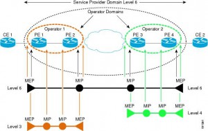
ME Maintenance Entity
MEG ME Group
MEL MEG Level
MEP MEG End Point
MIP MEG Intermediate Point

Eight MEG Levels are available to accommodate different network deployment scenarios:
• Customer role is assigned three MEG Levels: 7, 6, and 5.
• Provider role is assigned two MEG Levels: 4 and 3.
• Operator role is assigned three MEG Levels: 2, 1, and 0.

Transmission periods:
• 3.33 ms: Default transmission period for protection switching application (transmission rate of 300 frames/second).
• 10 ms: (Transmission rate is 100 frames/second).
• 100 ms: Default transmission period for performance monitoring application (transmission rate of 10 frames/second).
• 1 s: Default transmission period for fault management application (transmission rate of 1 frame/second).
• 10 s: (Transmission rate of 6 frames/minute).
• 1 min: (Transmission rate of 1 frame/minute).
• 10 min: (Transmission rate of 6 frames/hour).

Fault management
CCM Continuity Check Message
If no CCM frames from a peer MEP are received within the interval equal to 3.5 times the
receiving MEP’s CCM transmission period, loss of continuity with peer MEP is detected.

Ethernet Loopback function (ETH-LB) is used to verify connectivity of a MEP with a MIP or peer
MEP(s).
LBM LoopBack Message
LBR LoopBack Reply
LBR frame within 5 seconds.
Transaction ID from the same MEP may be repeated within one minute.
Unicast ETH-LB:
• To verify bidirectional connectivity of a MEP with a MIP or a peer MEP.
• To perform a bidirectional in-service or out-of-service diagnostics test between a pair of
peer MEPs. This includes verifying bandwidth throughput, detecting bit errors, etc.
The MIP or peer MEP is identified by its MAC address. This MAC address is encoded in the DA of the Unicast request frame. Transmitted only by MEP on the on-demand basis.
Multicast ETH-LB:
Multicast ETH-LB function is used to verify bidirectional connectivity of a MEP with its peer
MEPs. When Multicast-LB is invoked on a MEP, a Multicast frame with ETH-LB request information is sent from a MEP to other peer MEPs in the same MEG.  A MIP is transparent to the Multicast frames with ETH-LB request information.

Ethernet Link Trace function (ETH-LT)
• Adjacent Relation Retrieval – ETH-LT function can be used to retrieve adjacency
relationship between a MEP and a remote MEP or MIP. The result of running ETH-LT
function is a sequence of MIPs from the source MEP until the target MIP or MEP. Each
MIP and/or MEP is identified by its MAC address.
• Fault Localization – ETH-LT function can be used for fault localization. When a fault (e.g.,
a link and/or a device failure) or a forwarding plane loop occurs, the sequence of MIPs
and/or MEP will likely be different from the expected one. Difference in the sequences
provides information about the fault location.
LTM Link Trace Message
LTR Link Trace Reply
LTR frames within 5 seconds.
Transaction ID from the same MEP may be repeated within one minute.
If the TTL field value is 0, the LTM frame is discarded.
Only LTM frames with the same MEG Level
As each network element, containing the MIPs or MEP, needs to be aware of the TargetMAC
address in the received LTM frame and associates it to a single egress port, in order for the MIP or MEP to reply, a Unicast ETH-LB to the TargetMAC address could be performed by a MEP before transmitting the LTM frame.

Ethernet Alarm Indication Signal function (ETH-AIS)
Suppress alarms following detection of defect conditions at the server (sub) layer. ETH-AIS is not expected to be applied in the STP environments.

Ethernet Remote Defect Indication function (ETH-RDI) can be used by a MEP to communicate to
its peer MEPs that a defect condition has been encountered.

Ethernet Locked Signal function (ETH-LCK) is used to communicate the administrative locking of a server (sub) layer MEP and consequential interruption of data traffic forwarding towards the MEP expecting this traffic. It allows a MEP receiving frames with ETH-LCK information to differentiate between a defect condition and an administrative locking action at the server (sub) layer MEP. An example of an application that would require administrative locking of a MEP is the out-of-service ETH-Test.

Ethernet Test Signal function (ETH-Test) is used to perform one-way on-demand in-service or outof-service diagnostics tests. This includes verifying bandwidth throughput, frame loss, bit
errors, etc.
Different Sequence Number must be used for every TST frame, no Sequence Number from the
same MEP may be repeated within one minute.

Ethernet Automatic Protection Switching function (ETH-APS) is used to control protection
switching operations to enhance reliability.

Ethernet Maintenance Communication Channel function (ETH-MCC) provides a maintenance
communication channel between a pair of MEPs. ETH-MCC can be used to perform remote
management.
A remote MEP, upon receiving a frame with ETH-MCC information and with a correct MEG
Level, passes the ETH-MCC information to the management agent which may additionally respond.

Ethernet Experimental OAM (ETH-EXP) is used for the experimental OAM functionality which can be used within an administrative domain on a temporary basis. Interoperability of the experimental OAM functionality is not expected across different administrative domains.

Ethernet Vendor Specific OAM (ETH-VSP) is used for vendor-specific OAM functionality which may be used by a vendor across its equipment. Interoperability of vendor-specific OAM functionality is not expected across different vendors’ equipment.

Performance monitoring
Frame Loss Measurement
(ETH-LM)

Frame Delay Measurement (ETH-DM)

Throughput measurement

BGP syncronization

When this is the case, the router ID of the OSPF router acting as the Autonomous System Boundary Router (ASBR) for the redistributed BGP routes must also be the router ID of the advertising IBGP speaker for the same prefix. The route reflector cluster list should match the two previously mentioned router IDs as well.

uRPF

uRPF does have additional features. The first one is uRPF exemptions and violation logging. With this feature, you may specify a standard or extended access-list as follows:

ip verify unicast source reachable-via [rx|any] <ACL-NUM>

The uRPF feature consults this access-list for packets violating the uRPF condition. If the ACL permits a packet, it is allowed to pass through. If the ACL denies the packet, the router drops it. You may use the log keyword to log the packets allowed or denied by the uRPF access-list.

BGP dampening

Is an evil! But 😉


Formula (Really Madly Hate! 😉

max-penalty = reuse-limit * 2 (max-suppress-time / half-life )

Command:

bgp dampening half-life reuse-limit suppress-limit maximum-suppress-time

Defaults:
The default penalty increase for a route flap is 1000. If the route attributes are the only change, the penalty increase is 500. This value is hard-coded.
The penalty on the route is reduced every 5 seconds.
The router checks for prefixes to unsuppress every 10 seconds.

bgp dampening 15 750 2000 60
(max penalty = 6000)

802.1X Authentication Using EAP

Extensible Authentication Protocol

one-time passwords (OTP) per RFC 2289

  • Supplicant: The 802.1X driver that supplies a username/password prompt to the user and
    sends/receives the EAPoL messages
  • Authenticator: Translates between EAPoL and RADIUS messages in both directions, and
    enables/disables ports based on the success/failure of authentication
  • Authentication server: Stores usernames/passwords and verifies that the correct values were submitted before authenticating the user
Protocol over LAN (EAPOL), CDP and STP allowed before authenticated.


IPv6 First Hop Security

IPv6 RA Guard rejects fake RA messages coming from host (non-router) ports (not sure whether it handles all possible IPv6 header fragmentation attacks). Interestingly, it can also validate the contents of RA messages (configuration flags, list of prefixes) received through router-facing ports, potentially giving you a safeguard against an attack of fat fingers.

DHCPv6 Guard blocks DHCPv6 messages coming from unauthorized DHCPv6 servers and relays. Like IPv6 RA Guard it also validates the DHCPv6 replies coming from authorized DHCPv6 servers, potentially providing protection against DHCPv6 server misconfiguration.

IPv6 Snooping and device tracking builds a IPv6 First-Hop Security Binding Table (nicer name for ND table) by monitoring DHCPv6 and ND messages as well as regular IPv6 traffic. The binding table can be used to stop ND spoofing (in IPv4 world we’d call this feature DHCP Snooping and Dynamic ARP Inspection).

IPv6 Source Guard uses the IPv6 First-Hop Security Binding Table to drop traffic from unknown sources or bogus IPv6 addresses not in the binding table. The switch also tries to recover from lost address information, querying DHCPv6 server or using IPv6 neighbor discovery to verify the source IPv6 address after dropping the offending packet(s).

IPv6 Prefix Guard is denies illegal off-subnet traffic. It uses information gleaned from RA messages and IA_PD option of DHCPv6 replies (delegated prefixes) to build the table of valid prefixes.

Configuration:

Access-lists

CAT2(config)# ipv6 access-list ACCESS_PORT
CAT2(config-ipv6-acl)# remark Block all traffic DHCP server -> client
CAT2(config-ipv6-acl)# deny udp any eq 547 any eq 546
CAT2(config-ipv6-acl)# remark Block Router Advertisements
CAT2(config-ipv6-acl)# deny icmp any any router-advertisement
CAT2(config-ipv6-acl)# permit any any
CAT2(config-ipv6-acl)# !
CAT2(config-ipv6-acl)# interface gigabitethernet 1/0/1
CAT2(config-if)# switchport
CAT2(config-if)# ipv6 traffic-filter ACCESS_PORT in

RA Guard

Switch(config)# ipv6 nd raguard policy POLICY-NAME
! Defines the RA Guard policy name
Switch(config-ra-guard)# device-role {host | router}
Switch(config)# interface INTERFACE
Switch(config-if)# ipv6 nd raguard attach-policy POLICY-NAME

DHCPv6 Guard

CAT1(config)# ipv6 access-list acl1
CAT1(config-ipv6-acl)# permit host FE80::A8BB:CCFF:FE01:F700 any
CAT1(config-ipv6-acl)# ipv6 prefix-list abc permit 2001:0DB8::/64 le 128
CAT1(config)# ipv6 dhcp guard policy pol1
CAT1(config-dhcp-guard)# device-role server
CAT1(config-dhcp-guard)# match server access-list acl1
CAT1(config-dhcp-guard)# match reply prefix-list abc
CAT1(config-dhcp-guard)# preference min 0
CAT1(config-dhcp-guard)# preference max 255
CAT1(config-dhcp-guard)# trusted-port
CAT1(config-dhcp-guard)# interface GigabitEthernet 1/0/1
CAT1(config-if)# switchport
CAT1(config-if)# ipv6 dhcp guard attach-policy pol1 vlan add 1
CAT1# show ipv6 dhcp guard policy pol1

BGP

Confederations

LPref, MED and next-hop are kept across sub-AS eBGP!

network 1.0.0.0/24 backup – set distance 200

MED, Local-pref, NLRI are sent as TLVs.

When an IGP (in this example OSPF) route is redistributed in to BGP it is considered locally generated by BGP and gets assigned a weight of 32768.

Best Path Selection

AIGP – optiona notransitive 8 octet. If AIGP is configured AND the bgp bestpath aigp ignore command is not configured, the decision process considers the AIGP metric.

An AS_SET counts as 1, no matter how many ASs are in the set.

AIGP after Local Preference. AIGP metric reflects IGP cost. Lowest wins.
BGP prefers the path with the AIGP attribute by default.


Timers
The default BGP ConnectRetry timer is 120 seconds. Only after this time passes does the BGP process check to see if the passive TCP session is established. If the passive TCP session is not established, then the BGP process starts a new active TCP attempt to connect to the remote BGP speaker. During this idle 120 seconds of the ConnectRetry timer, the remote BGP peer can establish a BGP session to it. Presently, the Cisco IOS ConnectRetry timer cannot be changed from its default of 120 seconds.

Communities
Internet == 0:0 == match all; no such community in RFC

Redistribute & MED
— If the injected BGP route, using the network or redistribute command, is
from an IGP, the BGP MED is derived from the IGP metric.
— If the injected BGP route (using the network or redistribute command) is
from a connected route, the BGP MED is set to 0.
— If the route is injected by the aggregate-address command, MED is not set.

BGP GR
Capability 64
For IPv4, the end-of-RIB marker is a BGP Update message with no reachable NLRI and
empty withdrawn NLRI. Additional address families indicate the end-of-RIB with a BGP
Update containing only the MP_UNREACH_NLRI attribute with no withdrawn routes for
that AFI/SAFI.
Restart Time indicates how long a peer of the restarting router should maintain prefix
information received from the restarting router. The restart time should be less than the holdtime for the BGP peer.
The reception of a BGP-GR capability with no AFI/SAFI information indicates that the sending peer supports the end-of-RIB marker and can support peers that can maintain forwarding state and that want to utilize BGP-GR. The reception of a BGP-GR capability with AFI/SAFI information indicates that the sending peer wants to perform BGP-GR for the included AFI/SAFIs.
Mark all prefixes as stale.
After restart:
The receiving BGP router sends the BGP-GR capability to the restarting BGP router, with
the Restart State set to 0, unless the receiving BGP router also is reset. The receiving BGP
router receives a BGP-GR capability from the restarting BGP router with a Restart State of 1.
This triggers the receiving BGP router to send the initial routing update, followed by the
end-of-RIB marker.

Performance Routing (PfR)

Phases wheel:

  1. Profile/Learning Phase – learn flows with high latency and throughput = monitored traffic classes (MTC).
  2. Measure Phase – Collect and compute performance metrics for MTC.
  3. Apply Policy Phase – create low and high thresholds defining in-policy and out-of-policy (OOP) categories.
  4. Control Phase – influence by manipulating routing or PBR.
  5. Verify Phase – verify OOP event to make adjustmets to bring back in-policy.

Inrefaces types:

  1. Internal – connect to the internal network with Master Controller
  2. External – used to transmit packets out of the local network. Interfaces that monitored. At least 2.
  3. Local – used in the formation of the control plane mechanism. Source to communicate with Master Controller.

Operational Roles

Mandatory authentication – key-chains!

Master Controller (MC) and Border router (BR).

A single MC can support up to ten individual border routers
or up to 20 managed exit interfaces (external interfaces).


Passive monitoring: Measuring the performance metrics of interesting prefixes while the traffic is flowing through the device using NetFlow technology

Active monitoring: Creating a stream of synthetic traffic replicating the interesting traffic classes as closely as possible to measure the performance metrics of the synthetic traffic; uses Cisco integrated IP SLAs technology

Both active and passive monitoring: Combining both active and passive monitoring to generate a more complete picture of traffic flows within the network

Route redistribution and summarization

Order of metric operations:

  1. Call a route map from the redistribute command, with the route map using the set
    metric command. This method allows different metrics for different routes.
  2. Use the metric option on the redistribute command. This sets the same metric for
    all routes redistributed by that redistribute command.
  3. Use the default-metric command under the router command. This command sets the
    metric for all redistributed routes whose metric was not set by either of the other
    two methods.
IGP Default Metric Default (and Possible) Metric Types
RIP
EIGRP External
OSPF 20/1 E2 (E1 or E2)
IS-IS 0 L1 (L1, L2, L1/L2, or external)

Distance

distance { distance-value neigh-ip-address { wildcard-mask } [ ip-standard-list ]
[ ip-extended-list ]
distance distance
distance eigrp internal-distance external-distance
distance ospf {[ intra-area dist1 ] [ inter-area dist2 ] [ external dist3 ]}
distance bgp external internal local

Default routing

RIP EIGRP OSPF
redistribute static Yes Yes No
default-information originate Yes No Yes
ip default-network Yes Yes No
Summary routes No Yes No

If a static route to 0.0.0.0/0 is in the local routing table, the default-information originate command does NOT cause RIP to inject a default. Redistribute static should be used in that case.

Cisco documentation advises against using route summarization to create a default route.


OSPF


Change the cost of the default route advertised into a stub or NSSA area.

area 1 default-cost 123


Type7 to Type5 by ABR with highest RID.
Forwarding-address not ZERO in Type7 and Type7 to Type5. Recurse to Type3 and not Type4.
The ABR connected to the NSSA takes the type 7 LSAs and converts them into type 5 LSAs, which makes it an ASBR as well. Therefore this ABR doesn’t generate a type 4 LSAs for itself. The type 4 LSA is rather generated by the other ABRs connected to other areas.
Per the NSSA area RFC, the use of FA is mandatory with these LSAs. The reason is that there is only one 7-to-5 translating ABR and this might result in suboptimal routing without the use of FA.
FA SHOULD be reachable via OSPF.

(config-router)#area 2 nssa translate type7 ?
  always       Always translate LSAs on this ABR
  suppress-fa  Suppress forwarding address in translated LSAs

area 1 nssa default-information-originate – generates Type7 default with metric 1

default-information originate [always] – generates Type5 default with metric 1

Redistribution

Optional subnets. Metric 1 for BGP, 20 for others.

  default-metric         Set metric of redistributed routes


LSInfinity
http://thenetworksherpa.com/ospf-lsinfinity-not-equal-lsinfinity/

Hidden commands

sh ip ospf delete
show ip ospf maxage-list


DHCP options

Option Description Command
Option 12
Name of the client ip dhcp client hostname host-name
Option 51
Request lease time ip dhcp client lease days [hours] [minutes]
Option 55
Turn off some of the requested options [no] ip dhcp client request option-name
Option 60
Vendor class identifier string ip dhcp client class-id { ascii string | hex string }
Option 61
Specify unique client identifier ip dhcp client client-id { interface-name| ascii string | hex string }

DHCP Client Identifier = hardware type (usually 01) + client hardware address.

Client Identifier NOT used for BOOTP. Solely for DHCP.

URPF with ACL configured order of operations

Step 1 Input ACLs configured on the inbound interface are checked.

Step 2 Unicast RPF checks to see if the packet has arrived on the best return path to the source, which it does by doing a reverse lookup in the FIB table.

Step 3 CEF table (FIB) lookup is carried out for packet forwarding.

Step 4 Output ACLs are checked on the outbound interface.

Step 5 The packet is forwarded.

EIGRP

K values and Classic and Wide metrics

K1 trough K5. By default K1 and K3 == 1; all others – 0 (only BW and Delay re taken into account).

  • metric = [k1 * BW + (k2 * BW)/(256 – load) + k3 * delay]
  • If k5 != 0, metric = metric * [k5/(reliability + k4)]

Scaled Bandwidth = 10^7/minimum interface bandwidth (in kilobits per second) * 256
Delay is in tens of microseconds * 256. hexadecimal FFFFFFFF (decimal 4294967295) – unreachable.
Reliability is given as a fraction of 255. That is, 255 is 100 percent reliability or a perfectly stable link.
Load is given as a fraction of 255. A load of 255 indicates a completely saturated link.

  • metric = [k1 * Throughput + (k2 * Troughput)/(256 – load) + k3 * Latency + k6 * ExtM]
  • If k5 != 0, metric = metric * [k5/(reliability + k4)]

BW is now Throughput * 65536
DLY is now Latency * 65536
ExtM are the extended metrics (Jitter, Energy, and Quiescent Energy).

RIB is capable of handling only 32-bit metrics. Default is to scale * 1/128

metric rib-scale [1-255]

 Packet format

Encapsulated directly to IP with proto number 88;

+-+-+-+-+-+-+-+-+-+-+-+-+-+-+-+-+-+-+-+-+-+-+-+-+-+-+-+-+-+-+-+-+
|Header Version | Opcode        |           Checksum            |
+-+-+-+-+-+-+-+-+-+-+-+-+-+-+-+-+-+-+-+-+-+-+-+-+-+-+-+-+-+-+-+-+
|                             Flags                             |
+-+-+-+-+-+-+-+-+-+-+-+-+-+-+-+-+-+-+-+-+-+-+-+-+-+-+-+-+-+-+-+-+
|                        Sequence Number                        |
+-+-+-+-+-+-+-+-+-+-+-+-+-+-+-+-+-+-+-+-+-+-+-+-+-+-+-+-+-+-+-+-+
|                    Acknowledgement number                     |
+-+-+-+-+-+-+-+-+-+-+-+-+-+-+-+-+-+-+-+-+-+-+-+-+-+-+-+-+-+-+-+-+
|  Virtual Router ID              | Autonomous system number    |
+-+-+-+-+-+-+-+-+-+-+-+-+-+-+-+-+-+-+-+-+-+-+-+-+-+-+-+-+-+-+-+-+

Flags – 32-bit field indicating specific flags: 0x1 = Init (used during initial adjacency buildup), 0x2 = Conditional Receive (used by RTP to allow this message to be received only by a subset of receivers), 0x4 = Restart (indicates that a router has restarted), 0x8 = End-of-Table (indicates that the transmission of the entire EIGRP database is complete).

Opcode – 4 bit field. 1 = Update, 3 = Query, 4 = Reply, 5 = Hello/Ack, 10 = SIA Query, 11 = SIA Reply.

Virtual router ID – 0x1 = Unicast Address Family, 0x2 = Multicast Address Family, 0x8000 = Unicast Service Address Family

TLVs: 
0x0001 EIGRP Parameters (General TLV Types)
0x0002 Authentication Type (General TLV Types)
0x0003 Sequence (General TLV Types)
0x0004 Software Version (General TLV Types)
0x0005 Next Multicast Sequence (General TLV Types)
0x0102 IPv4 Internal Routes (IP-Specific TLV Types)
0x0103 IPv4 External Routes (IP-Specific TLV Types)
0x0402 IPv6 Internal Routes (IP-Specific TLV Types)
0x0403 IPv6 External Routes (IP-Specific TLV Types)
0x0602 Multi Protocol Internal Routes (AFI-Specific TLV Types)
0x0603 Multi Protocol External Routes (AFI-Specific TLV Types)

Packet types

  • Hello

    224.0.0.10 in IPv4, and FF02::A in IPv6. 5 seconds; 60 seconds for NBMA with the bandwidth setting of 1544 kbps and less;

  • Acknowledgement

    always unicasted to the sender of the acknowledged packet. Hello packet with an empty body (that is, no TLVs) and having a non-zero Acknowledgment number field.

  • Update
     Multicast or unicast. During a new adjacency buildup – unicast, then – multicast. Might choose to use multicast for efficiency (DMVPN). On point-to-point interfaces and for statically configured neighbors – always unicast. Retransmit the Update as unicast to the unresponsive neighbor.
  • Query

    Involve neighbors in the task of searching for the best route toward a destination. ACK does not constitute a response to the Query message, only an acknowledgment that the Query has been received. Multicast on multiaccess, unicast on point-to-point and static neighbors; unicast to unresponsive neighbor.

  • Reply

    Response to Query. Always unicasted to the originator.

  • SIA-Query
  • SIA-Reply

    If the neighbor is reachable and is still engaged in the diffusing computation for the destination specified in the SIA-Query, it will immediately respond with an SIA-Reply packet. As a result, the timer that governs the maximum time a diffusing computation is allowed to run is reset, giving the computation extra time to finish. Both are unicast.

Update, Query, Reply, SIA-Query, and SIA-Reply packets are also called reliable packets.

Next Multicast Sequence TLV contains the upcoming sequence number of the next reliable multicasted message. The Sequence TLV contains a list of all lagging neighbors by their IP address.  A neighbor receiving this Sequenced Hello packet and not finding itself in the Sequence TLV will know that it is expected to receive the upcoming multicast packet, and will put itself into a so-called Conditional Receive mode (CR-mode).  Sending router will send the next multicast packet with the CR flag set in its Flags field. Routers in CR-mode will process this packet as usual and then exit the CR-mode; routers not in CR-mode will ignore it.

multicast flow timer – time to wait for ACK
retransmission timeout (RTO) – time between the sub- sequent unicasts. Typically 6 times the SRTT. Min 100ms, max 5000 ms.
smooth round-trip time (SRTT) –  average elapsed time, measured in milliseconds, between the transmission of a reliable packet to the neighbor and the receipt of an acknowledgment

If a reliable packet is not acknowledged before 16 retransmissions and the Hold Timer duration has passed, re-initialize the neighbor.

Router Adjacencies

Parameters to match:

  • EIGRP Authentication Parameters (if configured)
  • EIGRP K-Values
  • EIGRP Autonomous System (AS) Number
  • Use of primary addresses for EIGRP neighbor relationships
  • Use of the common IP network address on a single subnet

Timers (do not need to match):
Hello – 5 seconds60 seconds for NBMA with the bandwidth setting of 1544 kbps and less;
Hold – 15 or 180 seconds, depending on the interface type. Changing Hello does NOT result recalculation of Hold.

Process:
add image from page 377 here.

DUAL

  • Reported Distance (RD) (or Advertised Distance) corresponds to the current best distance of the particular neighbor to the destination.
  • Computed Distance (CD) shows the total metric of reaching the destination over the particular neighbor. RD of the neighbor + the cost of the link to the neighbor.
  • FD is a record of the lowest known distance since the last transition from the Active to Passive state. FD is a historical record, or a historical copy, of the smallest known CD toward a particular destination, with the history starting anew with the last Active-to-Passive transition. Not necessarily equal to CD. Internal value. Not advertised.
  • Feasibility condition – any neighbor whose Reported Distance is strictly smaller than this router’s Feasible Distance cannot form a routing loop. RD < FD. Sometimes called the Source Node Condition.

Feasible Successors – neighbors that pass the FC.
Successors – neighbors that report the least CD.

Local & diffusing computations.

After a failure:
1. Choose the neighbor that provides the least CD.
2. If it meets FCstart using it right away; if it does notput route into Active .

Stuck-In-Active – torn down all neighbors that did not reply. Consider that they responded with an infinite metric.
Active timer – 3 min; 1 – 65535.

(config-router)#timers active-time

If a neighbor does not respond to a Query message with its Reply within half of the Active timer time, the router will send the neighbor a SIA-Query message. Wait for SIA-Reply within the next half of the Active timer. Receiving an SIA-Reply allows the Active timer to be reset.  Three SIA-Queries can be sent, each after half of the Active timer.

Named Mode

Starting from 15.0(1)M.
Multiple processes named and classic mix.
All EIGRP-related commands outside the named mode (such as per-interface commands) will be ignored if configured.

  • Address Family (AF) section: the AS is part of AF definition
  • Per-AF-interface section:  af-interface default holds settings for all IFs.
    • passive-interface – do not form adj
    • shutdown – completely ignore
  • Per-AF-topology section: Multi Topology Routing (MTR) in EIGRP. topology base is always present.

Router ID

4 Byte. Manually or highest IP of Lo.
Can be different for each AF.
External routes tagged by RID. Dropped if own RID received.
Recent IOSs tag internal routes also.
0.0.0.0 and 255.255.255.255 disallowed.

(config-router)#eigrp router-id

Unequal-Cost Load Balancing

variance multiplier

or

topology base
     variance multiplier

Defines how many times worse than the best path a route through a Feasible Successor can be.

Add-Path Support

Since IOS 15.3.2(T)
Must be installed in touting table (maximum-path , metric ).
Split Horizon must  be deactivated on the multipoint tunnel interface (DMVPN).
Only in named mode. Range 1 – 4.

R1-Hub(config)# router eigrp CCIE
R1-Hub(config-router)# address-family ipv4 unicast autonomous-system 1 
R1-Hub(config-router-af)# topology base 
R1-Hub(config-router-af-topology)# variance 1 
R1-Hub(config-router-af-topology)# maximum-paths 6 
R1-Hub(config-router-af-topology)# exit
R1-Hub(config-router-af)# af-interface Tunnel0 
R1-Hub(config-router-af-interface)# no split-horizon 
R1-Hub(config-router-af-interface)# no next-hop-self 
R1-Hub(config-router-af-interface)# add-paths 4

The Variance (Unequal Cost Load Balancing) and Add-Path features are not compatible with each other.

no next-hop-self no-ecmp-mode is recommended with the Add-Path feature if the hub uses multiple tunnel interfaces to reach the spoke sites (avoid setting NHS when the route is reachable via other tunnel if any of these routes’ Successors can be reached over the interface on which the route is going to be readvertised).

Stub Routing

RIP and RIPng

RIPv2

224.0.0.9 UDP port 520
No hello, RIPv2 relies on the regular full routing updates instead
Update interval 30 seconds
Full updates each interval. For on-demand circuits, allows RIPv2 to
send full updates once, and then remain silent until changes occur, per
RFC 2091
When route changes – triggered update.
Auth: plain-text + MD5
Route tags
Next-hop field

Timers:
Update 30 s
Invalid after timer per route default 180 s
Holddown timer begins after a route has been declared invalid; default 180 s. The router starts advertising that route as unreachable, does not accept any updated information, and does not modify the routing table entry for that route.
Flushed after timer per route default 240 seconds; If the updates about the route from its next hop cease to be received and the Flushed after timer reaches its limit, the router removes the route from the routing table entirely.
The default timer setting actually does not allow the Holddown timer to completely expire. As a result, the effective Holddown period is only 60 seconds.

  router rip
      timers basic update invalid holddown flush

The RIP packet format is:

       0                   1                   2                   3
       0 1 2 3 4 5 6 7 8 9 0 1 2 3 4 5 6 7 8 9 0 1 2 3 4 5 6 7 8 9 0 1
      +-+-+-+-+-+-+-+-+-+-+-+-+-+-+-+-+-+-+-+-+-+-+-+-+-+-+-+-+-+-+-+-+
      |  command (1)  |  version (1)  |       must be zero (2)        |
      +---------------+---------------+-------------------------------+
      |                                                               |
      ~                         RIP Entry (20)                        ~
      |                                                               |
      +---------------+---------------+---------------+---------------+

RIP Entry :

       0                   1                   2                   3
       0 1 2 3 4 5 6 7 8 9 0 1 2 3 4 5 6 7 8 9 0 1 2 3 4 5 6 7 8 9 0 1
      +-+-+-+-+-+-+-+-+-+-+-+-+-+-+-+-+-+-+-+-+-+-+-+-+-+-+-+-+-+-+-+-+
      | address family identifier (2) |      route tag    (2)         |
      +-------------------------------+-------------------------------+
      |                        IPv4 address (4)                       |
      +---------------------------------------------------------------+
      |                        Subnet Mask  (4)                       |
      +---------------------------------------------------------------+
      |                        Next-hop addr (4)                      |
      +---------------------------------------------------------------+
      |                           metric (4)                          |
      +---------------------------------------------------------------+

A RIP message consists of a 4B-long header containing the command field (set to 1 for
Request, 2 for Response) and the version field (2 for RIPv2). The remaining two octets
are unused. The remainder of the message consists of routing entries, with each routing
entry occupying 20 octets in total. At most 25 routing entries can be placed into a single
RIP message. Each routing entry contains the address family identifier identifying the
format of the address information carried in the routing entry (only the value 2, IPv4—
also known as AF_INET—is commonly supported), route tag, and the route itself—its
address, netmask, recommended next hop, and metric.

A Request message is used to ask a neighbor to send a partial or a full RIP update immediately,
rather than waiting for the Update timer to expire, speeding the convergence. A
full RIP update is requested by a Request message containing exactly one routing entry
with the address family ID set to 0 and metric set to 16. Otherwise, if a Request message
lists one or more particular networks, only the update on these networks is requested.

RIPv2 increments the metric when sending updates; RIPng and EIGRP increment metrics when receiving updates.

RIPv2 uses autosummarization at classful network boundaries by default.

Cisco IOS enables the RIPv2 (and EIGRP) authentication process on a per-interface basis

interface Fa0/1
   ip rip authentication key-chain name
   ip rip authentication mode { text | md5 }

When authentication is enabled, the maximum number of prefixes that can be advertised
in a RIPv2 message is reduced by 1 to a value of 24. The first route entry in each RIPv2
message would be carrying 20 bytes of authentication data.

RIPNg

FF02::9 UDP port 521
No multiproto capability, so no address-family field.
Version field set to 1

Packet format:

       0                   1                   2                   3
       0 1 2 3 4 5 6 7 8 9 0 1 2 3 4 5 6 7 8 9 0 1 2 3 4 5 6 7 8 9 0 1
      +-+-+-+-+-+-+-+-+-+-+-+-+-+-+-+-+-+-+-+-+-+-+-+-+-+-+-+-+-+-+-+-+
      |  command (1)  |  version (1)  |       must be zero (2)        |
      +-+-+-+-+-+-+-+-+-+-+-+-+-+-+-+-+-+-+-+-+-+-+-+-+-+-+-+-+-+-+-+-+
      |                                                               |
      ~                Route Table Entry 1 (20)                       ~
      |                                                               |
      +-+-+-+-+-+-+-+-+-+-+-+-+-+-+-+-+-+-+-+-+-+-+-+-+-+-+-+-+-+-+-+-+
      |                                                               |
      ~                         ...                                   ~
      |                                                               |
      +-+-+-+-+-+-+-+-+-+-+-+-+-+-+-+-+-+-+-+-+-+-+-+-+-+-+-+-+-+-+-+-+
      |                                                               |
      ~                Route Table Entry N (20)                       ~
      |                                                               |
      +-+-+-+-+-+-+-+-+-+-+-+-+-+-+-+-+-+-+-+-+-+-+-+-+-+-+-+-+-+-+-+-+

Route Table Entry:

       0                   1                   2                   3
       0 1 2 3 4 5 6 7 8 9 0 1 2 3 4 5 6 7 8 9 0 1 2 3 4 5 6 7 8 9 0 1
      +-+-+-+-+-+-+-+-+-+-+-+-+-+-+-+-+-+-+-+-+-+-+-+-+-+-+-+-+-+-+-+-+
      |                                                               |
      ~                        IPv6 prefix (16)                       ~
      |                                                               |
      +---------------------------------------------------------------+
      |         route tag (2)         | prefix len (1)|  metric (1)   |
      +-+-+-+-+-+-+-+-+-+-+-+-+-+-+-+-+-+-+-+-+-+-+-+-+-+-+-+-+-+-+-+-+

The number of route entries in a RIPng message is limited only by the IPv6 MTU on the link, and the protocol itself poses no limitations on their count.

A next-hop RTE is identified by 0xFF in the metric field. The IPv6 prefix field contains the IPv6 address of the next-hop. The route-tag and prefix-len fields are set to 0.

  • Authentication or encryption by IPsec is not supported.
  • Split Horizon can be activated or deactivated only on a per-process basis
  • Passive interfaces are not supported.
  • Static (manual) neighbors cannot be configured (no neighbor command).
  • Per-process offset lists are not supported.


  • Multiple RIPng processes can be run on a router
  • Route Poisoning, as an enhancement of the Split Horizon mechanism, can be activated
    on a per-process basis.
  • Interfaces can be configured with a metric-offset value
  • The default route can be originated on a per-interface basis, including an option of
    suppressing all other updates over that interface.


CEF

ip cef and ipv6 cef

ip cef load-sharing algorithm and ipv6 cef load-sharing algorithm :

  • Original algorithm: As the name suggests, this is the original unseeded implementation prone to CEF polarization.
  • Universal algorithm: An improved algorithm using the Universal ID to avoid the CEF polarization.
  • Tunnel algorithm: A further improvement on the Universal algorithm especially suitable to environments where tunnels are extensively deployed, possibly resulting in arelatively small number of outer source/destination pairs. Avoids the CEF polarization. Might not be available for IPv6 CEF.
  • L4 port algorithm: Based on the Universal algorithm while also taking the L4 source and/or destination ports into account. Avoids the CEF polarization.

mls ip cef load-sharing (6500/7600):

Default ( default mls ip cef load-sharing ): Uses source and destination IP, plus the
Universal ID if supported by the hardware. Avoids CEF polarization.
Full ( mls ip cef load-sharing full ): Uses source IP, destination IP, source L4 port, and
destination L4 port. Does not use Universal ID. Prone to CEF polarization. However,
to alleviate its impact, this load-balancing algorithm causes the traffic to split equally
among multiple paths only if the number of paths is odd. With an even number of
parallel paths, the ratio of traffic split will not be uniform.
Simple ( mls ip cef load-sharing simple ): Uses source and destination IP only. Does
not use Universal ID. Prone to CEF polarization.
Full Simple ( mls ip cef load-sharing full simple ): Uses source IP, destination IP,
source L4 port, and destination L4 port. Does not use Universal ID. Prone to CEF
polarization. The difference from Full mode is that all parallel paths receive an equal
weight, and fewer adjacency entries in hardware are used. This mode avoids unequal
traffic split seen with Full mode.

unique-ID/universal-ID – adds a 32-bit router-specific value to the hash function (called the universal ID – this is a randomly generated value at the time of the switch boot up that can can be manually controlled).  This unique -ID concept does not work for an even number of equal-cost paths due to a hardware limitation, but it works perfectly for an odd number of equal-cost paths. In order to overcome this problem, Cisco IOS adds one link to the hardware adjacency table when there is an even number of equal-cost paths in order to make the system believe that there is an odd number of equal-cost links.

CEF Polarization: http://www.cisco.com/c/en/us/support/docs/ip/express-forwarding-cef/116376-technote-cef-00.html
CEF description: http://xgu.ru/wiki/Cisco_Express_Forwarding

IOS XE

This separation is achieved through the Forwarding and Feature Manager (FFM) and the
Forwarding Engine Driver (FED).
The FFM provides a set of APIs used to manage the control plane processes. The resulting
outcome is that the FFM programs the data plane through the FED and maintains all
forwarding states for the system. It is the FED that allows the drivers to affect the data
plane, and it is provided by the platform.

EEM

EEM uses event detectors and actions to provide notifications of
those events.

Event detectors that EEM supports include the following:
■ Monitoring SNMP objects
■ Screening Syslog messages for a pattern match (using regular expressions)
■ Monitoring counters
Timers (absolute time-of-day, countdown, watchdog, and CRON)
■ Screening CLI input for a regular expression match
Hardware insertion and removal
Routing table changes
IP SLA and NetFlow events
■ Generic On-Line Diagnostics (GOLD) events
■ Many others, including redundant switchover events, inbound SNMP messages, and
others
Event actions that EEM provides include the following:
■ Generating prioritized Syslog messages
Reloading the router
Switching to a secondary processor in a redundant platform
■ Generating SNMP traps
■ Setting or modifying a counter
■ Executing a Cisco IOS command
■ Sending a brief email message
Requesting system information when an event occurs
■ Reading or setting the state of a tracked object

RITE

IP Traffic Export, or Router IP Traffic Export (RITE), exports IP packets to a VLAN or
LAN interface for analysis. RITE does this only for traffic received on multiple WAN
or LAN interfaces simultaneously as would typically take place only if the device were
being targeted in a denial of service attack.

When configuring RITE, you enable it and configure it to direct copied packets to the
MAC address of the IDS host or protocol analyzer.

Inbound traffic (the default), outbound traffic, or both, and filtering on the number of
packets forwarded.

Edge# config term
Edge(config)# ip traffic-export profile export-this
Edge(config-rite)# interface fa0/0
Edge(config-rite)# bidirectional
Edge(config-rite)# mac-address 0018.0fad.df30
Edge(config-rite)# incoming sample one-in-every 20
Edge(config-rite)# outgoing sample one-in-every 100
Edge(config-rite)# exit
Edge(config)# interface fa0/1
Edge(config-if)# ip traffic-export apply export-this
Edge(config-if)# end
Edge#
%RITE-5-ACTIVATE: Activated IP traffic export on interface FastEthernet 0/1.

Netflow

The components of NetFlow are
Records: A set of predefined and user-defined key fields (such as source IP address,
destination IP address, source port, and so on) for network monitoring.
Flow monitors: Applied to an interface, flow monitors include records, a cache, and
optionally a flow exporter. The flow monitor cache collects information about flows.
Flow exporters: These export the cached flow information to outside systems (typically
a server running a NetFlow collector).
Flow samplers: Designed to reduce the load on NetFlow-enabled devices, flow samplers
allow specifying the sample size of traffic, NetFlow analyzes to a ratio of 1:2
through 1:32768 packets. That is, the number of packets analyzed is configurable
from 1/2 to 1/32768 of the packets flowing across the interface.

Version 1 (V1) is the original format supported in the initial NetFlow releases.

Version 5 (V5) is an enhancement that adds Border Gateway Protocol (BGP) autonomous system information and flow sequence numbers.

Version 8 (V8) is an enhancement that adds router-based aggregation schemes.

Version 9 is an enhancement to support different technologies such as Multicast, Internet Protocol Security (IPSec), BGP next-hops and Multi Protocol Label Switching (MPLS).

WCCP

  • UDP port 2048
  • content engines also communicate with each other using WCCP
  • Up to 32 content engines WCCPv1; lowest IP address – lead engine
  • Content engines request information on the cluster members from the WCCP
    router, which replies with a list. This permits the lead content engine to determine how
    traffic should be distributed to the cluster.
  • WCCPv1 – only HTTP port 80
  • WCCPv2:
    • TCP and UDP traffic other than TCP port 80 (FTP, Real Audio, Video)
    • Permits segmenting caching services provided by a caching cluster to a particular
      protocol or protocols
    • Supports multicast
    • Supports multiple routers (up to 32 per cluster)
    • MD5
    • Load distribution
    • Transparent error handling
ip wccp web-cache group-address 239.128.1.100 password cisco
! Next we configure an interface to redirect WCCP web-cache
! traffic outbound to a content engine:
int fa0/0
           ip wccp web-cache redirect out
! Finally, inbound traffic on interface fa0/1 is excluded from redirection:
int fa0/1
         ip wccp redirect exclude in
! filter traffic only for certain clients
ip wccp web-cache redirect-list access-list
! types of redirected traffic the router should accept
ip wccp web-cache group-list access-list

SNMP

  • UDP 161
  • UDP 162 (traps & informs)
SNMP Version Description
1 Uses SMIv1, simple authentication with communities, but used MIB-I originally.
2 Uses SMIv2, removed requirement for communities, added GetBulk and Inform messages, but began with MIB-II originally.
2c Pseudo-release (RFC 1905) that allowed SNMPv1-style communities with SNMPv2; otherwise, equivalent to SNMPv2.
3 Mostly identical to SNMPv2, but adds significantly better security, although it supports communities for backward compatibility. Uses MIB-II. MD5/SHA + DES.


RMON

Remote Monitoring, or RMON, is an event-notification extension of the SNMP capability
on a Cisco router or switch. RMON enables you to configure thresholds for alerting
based on SNMP objects, so that you can monitor device performance and take appropriate
action to any deviations from the normal range of performance indications.
RMON is divided into two classes: alarms and events.

rmon event 1 log trap public description Fa0.0RisingErrors owner config
rmon event 2 log trap public description Fa0.0FallingErrors owner config
rmon event 3 log trap public description Se0.0RisingErrors owner config
rmon event 4 log trap public description Se0.0FallingErrors owner config
rmon alarm 11 ifInErrors.1 60 delta rising-threshold 10 1 falling-threshold 5 2 
owner config
rmon alarm 20 ifInErrors.2 60 absolute rising-threshold 20 3 falling-threshold 10 
owner config

show rmon alarm
show rmon event

Jun 9 12:54:14.787: %RMON-5-FALLINGTRAP: Falling trap is generated
because the value of ifInErrors.1 has fallen below the fallingthreshold
value 5
Jun 9 12:55:40.732: %RMON-5-FALLINGTRAP: Falling trap is generated
because the value of ifInErrors.2 has fallen below the fallingthreshold
value 10

NTP

  • UDP 123
  • Modes: client (static/broadcast); server; symmetric active mode (ntp peer)

1) Peer – permits router to respond to NTP requests and accept NTP updates. NTP control queries are also accepted. This is the only class which allows a router to be synchronized by other devices.
2) Serve – permits router to reply to NTP requests, but rejects NTP updates (e.g. replies from a server or update packets from a peer). Control queries are also permitted.
3) Serve-only – permits router to respond to NTP requests only. Rejects attempt to synchronize local system time, and does not access control queries.
4) Query-only – only accepts NTP control queries. No response to NTP requests are sent, and no local system time synchronization with remote system is permitted.


HSRP, VRRP, and GLBP

HSRP

  • Virtual IP address and virtual MAC are active on the HSRP Active router.
  • 3 sec hello, 10 sec dead
  • 224.0.0.2 – V1
  • 224.0.0.102 – V2
  • Virtual MAC of 0000.0C07.ACxx (v1)
  • Virtual MAC of 0000.0c9f.fxxx for IPv4 (v2) and 0005.73a0.0xxx for IPv6 (v2)
  • Port UDP 1985 for IPv4
  • Port UDP 2029  for IPv6 
  • Clear-text & MD5 auth
  • MHSRP (administrative LB)
  • Only 1 standby, highest IP preemts standby.

VRRP

  • IP protocol number 112; TTL 255 – MUST
  • 224.0.0.18
  • 1 sec hello, 3 sec dead
  • Virtual MAC of 0000.5E00.01xx
  • Preempts by default
  • Group IP address is the interface IP address of one of routers (prio for the router will be 255)
  • Higest IP preempts; more than 1 standby
  • The priority value zero (0) has special meaning indicating that the current Master has stopped participating in VRRP. Backups quickly transition to master.

GLBP

  • UDP 3222
  • 224.0.0.102
  • 3 sec hello, 10 sec dead
  • 0007.B400.xxyy , where xx is the GLBP group number and yy is a different number for each router (01, 02, 03, or 04).
  • 1024 GLBP groups per physical interface and up to four AVF per GLBP group
  • If multiple gateways have the same priority (1-255), the gateway with the highest real IP address becomes the AVG; standby AVG election – same principle.
  • The Redirect timer (600 sec) determines how long will AVG continue to respond to ARP requests with the virtual MAC of the failed AVF. The Secondary Hold  (4 hours, 14400 sec) timer sets the amount of time the backup AVF will continue to accept packet for the virtual MAC address taken from the failed AVF.

ARP, RARP, BOOTP, and DHCP

Feature RARP BOOTP DHCP
Relies on server to allocate IP addresses Yes Yes Yes
Encapsulates messages inside IP and UDP so that they can be forwarded to a remote server No Yes Yes
Client can discover its own mask/gateway/DNS/download server No Yes Yes
Dynamic address assignment from a pool of IP addresses without requiring knowledge of client MACs No No Yes
Allows temporary lease of IP address No No Yes
Includes extensions for registering client’s FQDN with a DNS No No Yes


ARP

Ethernet proto type: 0x0806


RARP

Same old ARP message, but the ARP request lists a MAC address target of its own MAC address and a target IP address of 0.0.0.0. RARP server on the same subnet. ARP reply, after entering the configured IP address in the Source IP address field.


BOOTP

IP+UDP header.


DHCP

IP+UDP header.

DHCP relay:

  • set own IP address in gateway IP address (giaddr) field while relaying
  • change the destination IP address to a LAN broadcast, and forward the packet
    onto the client’s LAN

NAT order of operations


Inside-to-Outside Outside-to-Inside
  • If IPSec then check input access list
  • decryption – for CET (Cisco Encryption Technology) or IPSec
  • check input access list
  • check input rate limits
  • input accounting
  • redirect to web cache
  • policy routing
  • routing
  • NAT inside to outside (local to global translation)
  • crypto (check map and mark for encryption)
  • check output access list
  • inspect (Context-based Access Control (CBAC))
  • TCP intercept
  • encryption
  • Queueing
  • If IPSec then check input access list
  • decryption – for CET (Cisco Encryption Technology) or IPSec
  • check input access list
  • check input rate limits
  • input accounting
  • redirect to web cache
  • NAT outside to inside (global to local translation)
  • policy routing
  • routing
  • crypto (check map and mark for encryption)
  • check output access list
  • inspect CBAC
  • TCP intercept
  • encryption
  • Queueing

Note that the process is merely the same. But for inside process the NAT is performed after routing. As for outside the NAT if performed before routing. Which seems pretty logical 😉

QoS order of operations

Inbound
1. QoS Policy Propagation through Border Gateway Protocol (BGP) (QPPB)
2. Input common classification
3. Input ACLs
4. Input marking (class-based marking or Committed Access Rate (CAR))
5. Input policing (through a class-based policer or CAR)
6. IP Security (IPSec)
7. Cisco Express Forwarding (CEF) or Fast Switching

Outbound
1. CEF or Fast Switching
2. Output common classification
3. Output ACLs
4. Output marking
5. Output policing (through a class-based policer or CAR)
6. Queueing (Class-Based Weighted Fair Queueing (CBWFQ) and Low Latency Queueing (LLQ)), and Weighted Random Early Detection (WRED)

BGP order of preference

For inbound updates the order of preference is:
1. route-map
2. filter-list
3. prefix-list, distribute-list

For outbound updates the order of preference is:
1. filter-list
2. route-map | unsuppress-map
3. advertise-map (conditional-advertisement)
4. prefix-list|distribute-list
5. ORF prefix-list (a prefix-list the neighbor sends us)

Tunneling

Tunnel Mode  Topology and Address Space  Applications 
Automatic 6to4 Point-to-multipoint; 2002::/16 addresses Connecting isolated IPv6 island networks.
Manually configured Point-to-point; any address space; requires dual-stack support at both ends Carries only IPv6 packets across IPv4 networks.
IPv6 over IPv4 GRE Point-to-point; unicast addresses; requires dual-stack support at both ends Carries IPv6, CLNS, and other traffic.
ISATAP Point-to-multipoint; any multicast addresses Intended for connecting IPv6 hosts within a single site.
Automatic IPv4- compatible Point-to-multipoint; ::/96 address space; requires dual-stack support at both ends Deprecated. Cisco recommends using ISATAP tunnels instead. Coverage in this book is limited.
Tunnel Type  Tunnel Mode  Destination 
Manual ipv6ip  An IPv4 address
GRE over IPv4 gre ip  An IPv4 address
Automatic 6to4 ipv6ip 6to4  Automatically determined
ISATAP ipv6ip isatap  Automatically determined
Automatic IPv4-compatible ipv6ip auto-tunnel  Automatically determined

Automatic IPv4-Compatible Tunnels

The first 96 bits of the tunnel interface addresses are all 0s, and the remaining 32 bits are derived from an IPv4 address. These addresses are written as 0:0:0:0:0:0:A.B.C.D, or ::A.B.C.D, where A.B.C.D represents the IPv4 address.

Automatic 6to4 Tunnels

Per-packet basis to encapsulate traffic to the correct destination—thus its point-to-multipoint nature.

2002:border-router-IPv4-address::/48

This prefix-generation method leaves another 16 bits in the 64-bit prefix for numbering networks within a given site.

interface Ethernet2/0
 description Ethernet link to the outside world
 ip address 10.1.100.1 255.255.255.0
 !
 interface Tunnel0
 no ip address
 ipv6 address 2002:0a01:6401::1/64
 tunnel source Ethernet 2/0
 tunnel mode ipv6ip 6to4
 !
 ipv6 route 2002::/16 tunnel

ISATAP Tunnels

Treat underlying network like NBMA cloud. Point-to-multipoint operations.

[64-bit link-local or global unicast prefix]:0000:5EFE:[IPv4 address of the ISATAP link]

For example, let’s say that the IPv6 prefix in use is 2001:0DB8:0ABC:0DEF::/64 and the IPv4 tunnel destination address is 172.20.20.1. The IPv4 address, converted to hex, is AC14:1401. Therefore the ISATAP address is

2001:0DB8:0ABC:0DEF:0000:5EFE:AC14:1401

Interface MUST be configured to derive the IPv6 address using the EUI-64 method. EUI-64 addressing in a tunnel interface differs from EUI-64 on a nontunnel interface in that it derives the last 32 bits of the interface ID from the tunnel source interface’s IPv4 address.

By default, tunnel interfaces disable router advertisements (RA). However, RAs must be enabled on ISATAP tunnels to support client autoconfiguration (no ipv6 nd supress-ra).


IPv6

Autoconfig

IPv6 hosts can use stateless or stateful autoconfiguration. Stateless address autoconfiguration (SLAAC) uses IPv6 prefixes from Router Advertisement (RA) messages; stateful autoconfiguration uses DHCPv6.

  • Managed-Config-Flag tells the end-host to use DHCPv6 exclusively;
  • Other-Config-Flag tells the end-host to use SLAAC to get IPv6 address and DHCPv6 to get other parameters (DNS server address, for example).
  • Absence of both flags tells the end-host to use only SLAAC.

One might assume that setting managed-config-flag in RA messages forces IPv6 hosts to use DHCPv6. Wrong, the two flags are just a polite suggestion.


Address types

Address Purpose
FF00::/8 Multicast
FF70::/12 Embedded RP
FE80::/10 Link Local Unicast
FF02::1:FF00:0000/104 Solicited node address
2000::/3 Global Unicast
2001::/32 Teredo
2001:DB8::/32 Documentation rezerved
2002::/16 Automatic 6to4
FC00::/7 Unique Local

Solicited node address

In addition, IPv6 multicast uses a solicited-node group that each router must join for all of its unicast and anycast addresses. The format for solicited-node multicast addresses is

FF02::1:FF00:0000/104

Solicited-node addresses are built from this prefix concatenated with the low-order 24 bits (128 – 104 = 24) of the corresponding unicast or anycast address. For example, a unicast address of

2001:1AB:2003:1::CBAC:DF01
has a corresponding solicited-node multicast address of

FF02::1:FFAC:DF01


Multicast address

General multicast address format
Bits 8 4 4 112
Field prefix flags scope group ID


Multicast addresses in IPv6 always begin with FF as the first octet in the address, or FF00::/8. The second octet specifies the lifetime and scope of the multicast group. Lifetime can be permanent (0000) or temporary (0001). Scope can be local to any of the following:

  • Node – 0001
  • Link – 0010
  • Site – 0101
  • Organization – 1000
  • Global – 1110

EUI-64 Address Format

Ethernet hosts and Cisco routers with Ethernet interfaces use their 48-bit MAC addresses as a seed for EUI-64 addressing. But because the MAC address is 48 bits long and the EUI-64 process makes up the last 64 bits of an IPv6 address, the host needs to derive the other 16 bits from another source. The IEEE EUI-64 standard places the hex value FFFE into the center of the MAC address for this purpose. Finally, EUI-64 sets the universal/local bit, which is the 7th bit in the Interface ID field of the address, to indicate global scope.

Here is an example. Given the IPv6 prefix 2001:128:1F:633 and a MAC address of 00:07:85:80:71:B8, the resulting EUI-64 address is

2001:128:1F:633:207:85FF:FE80:71B8/64


ND Functions in IPv6

Message Type  Information Sought or Sent Source Address Destination Address  ICMP Type, Code 
Router Advertisement (RA) Routers advertise their presence and link prefixes, MTU, and hop limits Router’s link-local address FF02::1 for periodic broadcasts; address of querying host for responses to an RS 134, 0
Router Solicitation (RS) Hosts query for the presence of routers on the link. Address assigned to querying interface, if assigned, or :: if not assigned FF02::2 133, 0
Neighbor Solicitation (NS) Hosts query for other nodes’ link-layer addresses. Used for duplicate address detection and to verify neighbor reachability. Address assigned to querying interface, if assigned, or :: if not assigned Solicited-node multicast address or the target node’s address, if known 135, 0
Neighbor Advertisement (NA) Sent in response to NS messages and periodically to provide information to neighbors. Configured or automatically assigned address of originating interface Address of node requesting the NA or FF02::1 for periodic advertisements 136, 0
Redirect Sent by routers to inform nodes of better next-hop routers. Link-local address of originating node Source address of requesting node 137, 0

ICMPv6

  • two groups: error reporting messages and informational messages
  • RFC mandates configurable rate limiting of ICMPv6 error messages (ipv6 icmp error-interval – default 100 ms + 10 token buckets)

DHCPv6

To use stateful autoconfiguration, a host sends a DHCP request to one of two well-known IPv6 multicast addresses on UDP port 547:


    • FF02::1:2, all DHCP relay agents and servers
    • FF05::1:3, all DHCP servers

NAT

Name Location of Host  IP Address Space in Which Address Exists
Inside local Inside the network  Part of the enterprise IP address space – private IP
Inside global Inside the network  Part of the public IP address space
Outside local In the public Inet  Part of the enterprise IP address space – private IP
Outside global In the public Inet  Part of the public IP address space

These are key terms to help you understand static NAT:

  • NAT inside interface—The Layer 3 interface that faces the private network.
  •  NAT outside interface—The Layer 3 interface that faces the public network.
  •  Local address—Any address that appears on the inside (private) portion of the network.
  •  Global address—Any address that appears on the outside (public) portion of the network.
  •  Legitimate IP address—An address that is assigned by the Network Information Center (NIC) or service provider.
  •  Inside local address—The IP address assigned to a host on the inside network. This address does not need to be a legitimate IP address.
  •  Outside local address—The IP address of an outside host as it appears to the inside network. It does not have to be a legitimate address, because it is allocated from an address space that can be routed on the inside network.
  •  Inside global address—A legitimate IP address that represents one or more inside local IP addresses to the outside world.
  •  Outside global address—The IP address that the host owner assigns to a host on the outside network. The address is a legitimate address that is allocated from an address or network space that can be routed.

StackWise

  • Homogeneous stack
  • Mixed stack
    • mixed hadrware
    • mixed software
    • mixed hard and soft

A switch stack is identified in the network by its bridge ID and, if it is operating as a Layer 3 device, its router MAC address. The bridge ID and router MAC address are determined by the MAC address of the stack master. Every stack member is identified by its own stack member number .
The system-level features supported on the stack master are supported on the entire switch stack.

Master election:

  1. current master
  2. highest stack member priority value (1-15; def 15)
  3. switch that is not using the default interface-level configuration
  4. switch with the higher priority feature set and software image combination
    1. IP services crypto
    2. IP services non crtypto
    3. IP base crypto
    4. IP Base non crypto
  5. Longest up-time.
  6. lowest MAC

A stack master retains its role unless one of these events occurs:

  • The switch stack is reset. 
  • The stack master is removed from the switch stack.
  • The stack master is reset or powered off.
  • The stack master fails.
  • The switch stack membership is increased by adding powered-on standalone switches or switch stacks.

Stack members that are powered on within the same 20-second time frame participate in the stack master election and have a chance to become the stack master. Stack members that are powered on after the 20-second time frame do not participate in this initial election and become stack members. All stack members participate in re-elections.

PBR

  • source
  • destination
  • protocol type
  • incoming interface
  • length

Directions:

  • incoming – link level (ip policy route-map)
  • locally originated (ip local policy route-map)

set ip|ipv6 default next-hop|interface – attempts to route based on the routing table, and only if no match is found in the routing table, the packet will be handled by PBR

Point-to-Point Protocol & HDLC

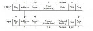
The ISO standard for the much older HDLC does not include a Type field, so the Cisco HDLC implementation adds a Cisco-proprietary 2-byte Type field to support multiple protocols over an HDLC link.

PPP framing (RFC 1662) defines the use of a simple HDLC header and trailer for most parts
of the PPP framing. PPP simply adds the Protocol field and
optional Padding field to the original HDLC framing. (The Padding field allows PPP to
ensure that the frame has an even number of bytes.)

PPP-HDLC

Feature HDLC PPP
Error detection? Yes Yes
Error recovery? No Yes
Standard Protocol Type field? No Yes
Default on IOS serial links? Yes No
Supports synchronous and asynchronous links? No Yes

PPP

  • RFC1661
  • includes an architected Protocol field
  • Link Control Protocol (LCP)
  • NCP for each L3 (IPCP, for example)

LCP features:

  • Link Quality Monitoring (LQM) (statistics about frames wo errors. if the percentage falls under configured value – frop the link). (ppp quality if command)
  • Looped link detection (send random magic number. if receive own number – drop the link)
  • Layer 2 load balancing (ML-PPP fragments the packet and sends the packet to each link. add header of 2 or 4 bytes for reassembly (sequence number and Flag bits designating the beginning and ending fragments)
  • Auth (pap, chap)

ML-PPP:

  • authenticated—Use the peer authenticated name as the bundle name. This option cannot support multiple clients using the same authentication username. (default option)
  • endpoint—Use the peer endpoint discriminator as the bundle name.
  • both—Use the peer authenticated name and endpoint discriminator as the bundle name.

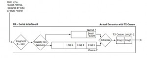
Link Fragmentation and Interleaving (LFI): prevent small, delay-sensitive packets from having to wait on longer, delay-insensitive packets to be completely serialized out an interface. LFI tools fragment larger packets, and then send the delay-sensitive packet after just a portion of the original, longer packet.

PPP-interleave

  • ppp multilink interleave
  • ppp multilink fragment-delay x : size = x * bandwidth; Note that the unit for the delay parameter is  milliseconds, so the units for the interface bandwidth must also be converted. Eg.:
    bandwidth 256
    ppp multilink fragment-delay 10
    The fragment delay is set to 10 ms, so the fragments will be of size (256,000 * 0.01) = 2560 bits = 320 bytes.
  • ppp multilink multiclass the sequence number is maintained per class and so the interleaved small packets also would have the multilink header and so could be ordered correctly. Resolves out-of-order issues with LFI.

Compression: payload, TCP header and/or RTP header.
Payload: Cisco IOS software supplies three different payload compression options for PPP, namely Lempel-Ziv Stacker (LZS), Microsoft Point-to-Point Compression (MPPC), and Predictor. LZ uses more CPU and less memory in comparison to Predictor, and LZ typically results in a better compression ratio. Once compression is configured (matching compress command), PPP starts the Compression Control Protocol (CCP), which is another NCP, to perform the compression negotiations and manage the compression process.

Feature Stacker MPPC Predictor
Uses LZ algorithm Yes Yes No
Supported on HDLC Yes No No
Supported on PPP Yes Yes Yes
Supported on Frame Relay Yes No No
Supports ATM and ATM-to-Frame Relay Service Interworking (using MLP)? Yes Yes Yes

RTP header compression compresses the IP/UDP/RTP headers (40 bytes) into 2
or 4 bytes. With G.729 in use, RTP header compression reduces the required bandwidth by
more than 50 percent.
TCP header compression compresses the combined IP and TCP headers, a combined
40 bytes, into 3 or 5 bytes.
It does this by saving the state of TCP connections at both ends of a link, and only sending the differences in the header fields that change.
ip tcp headercompression [passive] and ip rtp header-compression [passive]: use IPCP to initiate compression (or wait if passive).
Alternative method using an MQC policy map to create classbased header compression.

PAP

  • Client sends username and password
  • Server sends authentication-ack (if credentials are OK) or authentication-nak (otherwise)
    Description 1 byte 1 byte 2 bytes 1 byte Variable 1 byte Variable
    Authentication-request Code = 1 ID Length Username length Username Password length Password
    Authentication-ack Code = 2 ID Length Message length Message
    Authentication-nak Code = 3 ID Length Message length Message

    PAP packet embedded in a PPP frame. The protocol field has a value of C023 (hex).

    Flag Address Control Protocol (C023 (hex)) Payload (table above) FCS Flag

CHAP

  • After the completion of the link establishment phase, the authenticator sends a “challenge” message to the peer.
  • The peer responds with a value calculated using a one-way hash function on the challenge and the secret combined.
  • The authenticator checks the response against its own calculation of the expected hash value. If the values matches, the authenticator acknowledges the authentication; otherwise it should terminate the connection.
  • At random intervals the authenticator sends a new challenge to the peer and repeats steps 1 through 3.
    Description 1 byte 1 byte 2 bytes 1 byte Variable variable
    Challenge Code = 1 ID Length Challenge Length Challenge value Name
    Response Code = 2 ID Length Response Length Response value Name
    Success Code = 3 ID Length Message
    Failure Code = 4 ID Length Message

The Challenge packet has a Value field which contains a variable stream of octets (a random value). The Challenge packet also has a Name field which contains the hostname of the router transmitting the packet.

The “hash” that is generated in an outgoing PPP CHAP Response is created as a combination of three variables, and without knowing all three values the Hash Response cannot be generated:

  • A router’s Hostname
  • The configured PPP CHAP password
  • The PPP CHAP Challenge value

This generates a one-way hash value and set in the Value field of the Response packet which is sent back to the authenticator. The Name field of the Response packet is set to the hostname of the peer router.

CHAP packet embedded in a PPP frame. The protocol field has a value of C223 (hex).

http://www.cisco.com/c/en/us/td/docs/ios/qos/configuration/guide/15_1/qos_15_1_book/header_compression.html
http://www.effnet.com/pdf/uk/Whitepaper_Header_Compression.pdf

Very nice explanation of interleaving:
https://networklessons.com/quality-of-service/ppp-multilink-lfi/

Most voice codecs require a maximum delay of 10 ms between the different VoIP packets. Let’s say the serial link offers 128 Kbit of bandwidth…how long would it take to send a voice packet that is about 60 bytes?

60 bytes * 8 = 480 bits / 128.000 = 0.00375.

So it takes roughly 3.7 ms to send the voice packet which is far below the required 10 ms. We can run into issues however when we also send data packets over this link. Let’s say we have a 1500 bytes data packet that we want to send over this link:

1500 bytes * 8 = 12.000 / 128.000 = 0.093.

DHCP format

Table 1 BOOTP Request and Reply Format
Field Bytes Name Description
op 1 OpCode Identifies the packet as a request or reply. 1=BOOTREQUEST and 2=BOOTREPLY.
htype 1 Hardware Type Specifies the network hardware type.
hlen 1 Hardware Length Specifies the length hardware address length.
hops 1 Hops The client sets the value to zero and the value increments if the request is forwarded across a router.
xid 4 Transaction ID A random number that is chosen by the client. All DHCP messages exchanged for a given DHCP transaction use the ID (xid).
secs 2 Seconds Specifies number of seconds since the DHCP process started.
flags 2 Flags Indicates whether the message will be broadcast or unicast.
ciaddr 4 Client IP Address Used when the client is aware of the IP address as in the case of the Bound, Renew, or Rebinding states.
yiaddr 4 Your IP Address If the client IP address is 0.0.0.0, the DHCP server places the offered client IP address in this field.
siaddr 4 Server IP Address If the client knows the IP address of the DHCP server, this field is populated with the DHCP server address. Otherwise, it is used in DHCPOFFER and DHCPACK from the DHCP server.
giaddr 4 Router IP Address The gateway IP address, filled in by the DHCP/BootP Relay Agent.
chaddr 16 Client MAC Address The DHCP client MAC address.
sname 64 Server Name The optional server hostname.
File 128 Boot Filename The boot filename.
Options Variable Option Parameters The optional parameters that can be provided by the DHCP server. RFC 2132 lists all possible options.

Ethernet

Great article with header description:
https://learningnetwork.cisco.com/docs/DOC-26145

https://en.wikipedia.org/wiki/Ethernet_frame

https://en.wikipedia.org/wiki/IEEE_802.1Q

The SNAP is an extension of the 802.2 LLC specified in the IEEE 802 Overview and Architecture document.[2] The 5-octet SNAP header follows the 802.2 LLC header if the destination SAP (DSAP) and the source SAP (SSAP) contain hexadecimal values of AA or AB:

802.2 LLC Header SNAP extension
DSAP SSAP Control OUI Protocol ID
1 octet 1 octet 1 or 2 octets 3 octets 2 octets

The SNAP header consists of a 3-octet IEEE Organizationally Unique Identifier (OUI) followed by a 2-octet protocol ID. If the OUI is hexadecimal 000000, the protocol ID is the Ethernet type (EtherType) field value for the protocol running on top of SNAP; if the OUI is an OUI for a particular organization, the protocol ID is a value assigned by that organization to the protocol running on top of SNAP.
SNAP is usually used with Unnumbered Information 802.2 protocol data units (PDUs), with a control field value of 3, and the LSAP values are usually hexadecimal AA, so the 802.2 LLC header for a SNAP packet is usually AA AA 03; however, SNAP can be used with other PDU types as well.
On Ethernet, the 8 octets occupied by the LLC and SNAP headers reduce the size of the available payload for protocols such as the Internet Protocol to 1492 bytes, compared to the use of the Ethernet II framing; therefore, for protocols that have EtherType values, packets are usually transmitted with Ethernet II headers rather than with LLC and SNAP headers. On other network types, the LLC and SNAP headers are required in order to multiplex different protocols on the link layer, as the MAC layer doesn’t itself have an EtherType field, so there’s no alternative framing that would have a larger available payload.

Spanning Tree

IEEE 802.D

  • Protocol ID: 0
  • Reserved multicast MAC address 0180.C200.0000 using IEEE 802.2 LLC SAP encapsulation with both SSAP and DSAP fields equal to 0x42
  • Ignore inferior PDUs until Max_Age-Message_Age
  • TCN originated out of root port. The designated bridge receives the TCN, acknowledges it, and generates another one for its own root port. Root will send config BPDU with TCN flag set for Forward_Delay+Max_Age. Switches reduce MAC address tables aging time to Forward_Delay once the receive configuration BPDU with TC bit set. Switch originating TCN will stop it once it receives TCN ACK from upstream bridge.

Timers:
Hello: 2s
Max_Age: 20s (info age out)
Forward_Delay: 15s (listening/learning states)
Message_age: Incremented every time a BPDU traverses a switch (so it might be compared to the hop count).(start at 0)
Convergence:
2xForward_Time (direct link falure)
2xForward_Time + (Max_Age-Message_Age) (inderect failure or BPDU timeout)

UplinkFast: Upon link failure immediately activate ALT path. Dummy mcast with known MACs as source. Set bridge PRIO and link COST to high values not to become transit.
FlexLink: Active/standby pair (switchport backup command). mac address-table move {receive|transmit} and switchport backup interface x/y mmu.
BackboneFast: Explicitly verify inferior BPDU info. RLQ queries out of all candidate paths to the current root. Root floods a positive RLQ response out of ALL its designated ports. Saves Max_Age time.
LoopGuard: If BPDUs are not received on a non-designated port (root or alternate), and loop guard is enabled, that port is moved into the STP loop-inconsistent blocking state.


PVST+

Cisco switch connects to an IEEE switch using a 802.1q trunk with default native VLAN (VLAN 1)

  • CST (Common Spanning Tree) is the spanning tree built by joining a single instance from PVST+ domain (VLAN 1 instance) with MST (Mono Spanning Tree) . the spanning tree of IEEE domain.
  • The PVST+ switch sends IEEE STP BPDUs corresponding to local VLAN 1 STP to IEEE MAC address as untagged frames across the link
  • Special new SSTP (shared spanning tree, synonym to PVST+) BPDUs are being sent to SSTP multicast MAC address 0100.0ccc.cccd also untagged. These SSTP BPDUs are encapsulated using IEEE 802.2 LLC SNAP header (SSAP=DSAP=”0xAA” and SNAP PID=”0x010B”). Special TLV with the source VLAN number. IEEE switches simply flood them through the respective VLAN topology. The reason for sending additional SSTP BPDUs across VLAN 1 is purely informational, to perform consistency checking. The idea is to inform all other potential Cisco switches attached to MST cloud about our native VLAN.
  • As for non-native VLANs (VLANs 2-4095) Cisco switch sends only SSTP BPDUs, tagged with respective VLAN number and destined to the SSTP MAC address.

Cisco switch connects to IEEE switch using 802.1q trunk with non-default native VLAN (e.g VLAN 100).

  • IEEE switch sends IEEE STP BPDUs to IEEE multicast MAC address and those BPDUs are processed by VLAN 1 (CST) STP instance in the Cisco switch.
  • PVST+ side (Cisco switch) sends untagged IEEE STP BPDUs corresponding to VLAN 1 (CST) STP to IEEE MAC address across the link.
  • At the same time, VLAN 1 BPDUs are replicated to SSTP multicast address, tagged with VLAN 1 number (to inform other Cisco switches that VLAN 1 is non-native on our switch).
  • Finally, BPDUs of the native VLAN instance (VLAN 100 in our case) are sent untagged using SSTP encapsulation and destination address.
  • As in Case 1 for the remaining non-native VLANs (VLANs 2-4095) Cisco switch sends SSTP BPDU only, tagged with respective VLAN tag and destined to the SSTP MAC address.

PVST+ is used on 802.1q trunks to tunnel PVST instances across an MST (mono spanning tree) cloud and build a CST consisting of PVST VLAN 1 and IEEE MST. PVST+ BPDUs contain special TLV with the source VLAN ID, which allows interconnected switches to detect inconsitencies or misconfigurations.


RSTP

IEEE 802.1W -> IEEE 802.1D-2004 standard
Protocol ID: 2

  • Simplified port states (discard -> learn -> forwarding)
  • New port roles (backup; edge)
  • Sync process

TCN only generated when non-edge link becomes forwarding. TCN causes MAC table to flush (per vlan/instance).
spanning-tree portfast default; if BPDU received – remove edge status.

Link types:
– p2p (full duplex) – use sync
– shared (half duplex) – fall back to legacy

Sync:
– elect local root port
– block all non-edge designated ports
– start sync on all designated ports

Hello’s == keepalives. This gives 6 second vs 20 second Max_Age of legacy.
Topology change:
Set tcWhile == Hello + 1s on all non-edge Designated and Root ports except of the one the TCN was received
Flush MAC learned on these ports
Send TCN on these ports every Hello seconds until tcWhile expires.


MSTP

IEEE 802.1S -> IEEE 802.1Q-2005 standard
Protocol ID: 3
Based on RSTP (same sync process, etc).
Max 65 instances.

Region:
1. Region Name
2. Revision number(16 bit)
3. Vlan to instance mapping(hash)

  • IST BPDU using special M-Records (one for every active MSTI) which carry root prio, designated bridge prio, port prio, root path cost in TLV.
  • Timer can only be tuned for IST. Other instances inherit it.
  • MSTP does not use MaxAge timer. Special field in BPDU – Remaining Hops. Root send BPDU with hop count equal to MaxHops (configurable value).
  • If upstream switch sends superior info but receives BPDU with designated bit set it blocks the downstream port and declares it as STP Dispute link.

Intra region:

  • Details of region are known within region.
  • Manual vlan to instance mapping.
  • Undefind vlans fall to CIST (MSTI0)

Inter region:

  • Details between regions are not known.
  • Regions are treated as virtual bridges.
  • Simplified inter-region calculations: MSTIs are collapsed into CIST

Inter region operations:

  • CIST Root is the bridge that has the lowest Bridge ID among ALL regions. This could be a bridge inside a region or a boundary switch in a region.
  • CIST Regional Root is a boundary switch elected for every region based on the shortest external path cost to reach the CIST Root. Path cost is calculated based on costs of the links connecting the regions, excluding the internal regional paths. CIST Regional Root becomes the root of the IST for the given region as well. Provides Master Port.
  • The CST connects all boundary ports and perceives every region as a single virtual bridge with the Bridge ID equal to CIST Regional Root Bridge ID.
  • Every region builds IST instance using the internal path costs using CIST Regional Root as the IST Root
  • Switches do not send M-Records (MSTI information) out of boundary ports, only CIST information.
  • Since MSTIs in every region are independent, any change affecting MSTI in one region will not affect MSTIs in other regions. This is a direct result of the fact that M-Record information is not exchanged between the regions. However, the CIST recalculations affect every region and might be slow converging.


Interoperability:

  • MST is backward compatible with 802.1D and 802.1W.
  • Behaves like inter-region MST.
  • CST Root must be within MSTP domain:
    • Either IST BPDU must be superior for all the VLANS
    • Either IST BPDU is inferior for VLAN 1 and identical or inferior of PVST+ BPDU from all other VLANs
  • MST-PVST+: replicate all IST BPDUs to PVST+ BPDUs for all active VLANs. VLAN 1 info in the opposite direction.

MISC

  • spanning tree guard root: recovers automatically if undesired BPDUs are not received MaxAge-MessageAge or 3xHello interval for RSTP
  • spanning tree bpdufilter default: applies on EdgePorts. 1 immediate BPDU and 10 more each hello interval are sent. If no BPDUs received – ceaase sending.
  • spanning tree bpdufilter enable: Interface command. Cease sending & receiving BPDUs unconditionally.
  • Global BPDU Guard supersedes Global BPDU filter. While port-level – vice verca
  • Bridge Assurance must be enabled on both sides. BPDUs as Hellos (even for blocking). BA-inconsistient blocking state.

Links:
http://blog.ine.com/2008/07/17/pvst-explained/
http://blog.ine.com/2009/03/07/understanding-stp-convergence-part-i/
http://blog.ine.com/2009/03/14/understanding-stp-conv-2/
http://www.cisco.com/c/en/us/support/docs/lan-switching/spanning-tree-protocol/12013-17.html
http://www.cs.princeton.edu/~chkim/papers/seattle_sigcomm08.pdf

UDLD

  • Helper for STP
  • Special frames sent to well-known MAC address 01:00:0C:CC:CC:CC
  • If no echo frame with our ID has been seen from the peer for a certain amount of time, the port is suspected to be unidirectional.
  • In Normal mode, if the physical state of port (as reported by Layer 1) is still up, UDLD marks this port as Undetermined, but does NOT shut down or disable the port, which continues to operate under it’s current STP status.
  • If UDLD is set to Agressive mode, once the switch loses it’s neighbor it actively tries to re-establish the relationship by sending a UDLD frame 8 times every 1 second. If the neighbor does not respond after that, port is considered to be unidirectional and brought to Errdisable state.
  • UDLD Aggressive will only brings link to errdisable state when it detects Bidirectional to Unidirectional state transition. This prevents link from becoming errdisabled when you configure Aggressive mode just on one side. The UDLD state of such link will be Unknown

Private Vlans

  • Promiscuous (“P”) port: Usually connects to a router. This port type is allowed to send and receive L2 frames from any other port on the VLAN
  • Isolated (“I”) port: This type of port is only allowed to communicate with “P”-ports . i.e., they are “stub” port. You commonly see these ports connecting to hosts.
  • Community (“C”) port: Community ports are allowed to talk to their buddies, sharing the same community (group) and to .P.-ports.
  • The Primary VLAN delivers frames downstream from the router (promisc port) to all mapped hosts.
  • The Isolated VLAN transports frames from the stub hosts upstream to the router
  • The Community VLANs allow bi-directional frame exchange withing a single group, in addition to forwarding frames upstream towards “P”-ports.
  • Ethernet MAC address learning and forwarding procedure remain the same, as well as broadcast/multicast flooding procedure within boundaries of primary/secondary VLANs.
Switch# configure terminal
 Switch(config)# vlan 20
 Switch(config-vlan)# private-vlan primary
 Switch(config-vlan)# exit
 Switch(config)# vlan 501
 Switch(config-vlan)# private-vlan isolated
 Switch(config-vlan)# exit
 Switch(config)# vlan 502
 Switch(config-vlan)# private-vlan community
 Switch(config-vlan)# exit
 Switch(config)# vlan 503
 Switch(config-vlan)# private-vlan community
 Switch(config-vlan)# exit
 Switch(config)# vlan 20
 Switch(config-vlan)# private-vlan association 501-503
 Switch(config-vlan)# end
 Switch(config)# show vlan private vlan
 Primary Secondary Type Ports
 ------- --------- ----------------- ------------------------------------------
 20 501 isolated
 20 502 community
 20 503 community
 20 504 non-operational
Switch# configure terminal
 Switch(config)# interface gigatibethernet0/22
 Switch(config-if)# switchport mode private-vlan host
 Switch(config-if)# switchport private-vlan host-association 20 501
 Switch(config-if)# end
Switch# configure terminal
 Switch(config)# interface gigatibethernet0/2
 Switch(config-if)# switchport mode private-vlan promiscuous
 Switch(config-if)# switchport private-vlan mapping 20 add 501-503
 Switch(config-if)# end

Etherchannel

Member ports must have same values for:

  • Speed & duplex
  • trunking/access mode, DTP mode
  • same access VLAN
  • same trunk type, allowed & native vlans
  • same STP cost per VLAN
  • no SPAN configured

Switch shuts down all physical ports when no interface port-channel [n] to avoid loop.
spanning-tree etherchannel guard misconfig for the same purposes (BPDUs received via both ports).
PAGP: 8 links max; 01:00 :0c:cc:cc:cc
LACP: 16 links max, 8 active max, 8 standby; 01:80:C2:00:00:02
channel-protocol: interface command. refuse any modes keywords other than configured under this command

CDP & LLDP

CDP

MCAST MAC: 0100.0ccc.cccc
Timers: 60 sec, 180 sec


LLDP

MCAST MAC: 01:80:c2:00:00:0e, or 01:80:c2:00:00:03, or 01:80:c2:00:00:00
EtherType: 0x88CC
Timers: 30 sec, 120 sec
TLVs:
-Port description TLV
-System name TLV
-System description TLV
-System capabilities TLV
-Management address TLV