Category Archives: Layer 2

Y.1731 CFM & PM

CFM

ME Maintenance Entity
MEG ME Group
MEL MEG Level
MEP MEG End Point
MIP MEG Intermediate Point

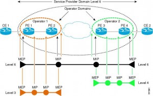
Eight MEG Levels are available to accommodate different network deployment scenarios:
• Customer role is assigned three MEG Levels: 7, 6, and 5.
• Provider role is assigned two MEG Levels: 4 and 3.
• Operator role is assigned three MEG Levels: 2, 1, and 0.

Transmission periods:
• 3.33 ms: Default transmission period for protection switching application (transmission rate of 300 frames/second).
• 10 ms: (Transmission rate is 100 frames/second).
• 100 ms: Default transmission period for performance monitoring application (transmission rate of 10 frames/second).
• 1 s: Default transmission period for fault management application (transmission rate of 1 frame/second).
• 10 s: (Transmission rate of 6 frames/minute).
• 1 min: (Transmission rate of 1 frame/minute).
• 10 min: (Transmission rate of 6 frames/hour).

Fault management
CCM Continuity Check Message
If no CCM frames from a peer MEP are received within the interval equal to 3.5 times the
receiving MEP’s CCM transmission period, loss of continuity with peer MEP is detected.

Ethernet Loopback function (ETH-LB) is used to verify connectivity of a MEP with a MIP or peer
MEP(s).
LBM LoopBack Message
LBR LoopBack Reply
LBR frame within 5 seconds.
Transaction ID from the same MEP may be repeated within one minute.
Unicast ETH-LB:
• To verify bidirectional connectivity of a MEP with a MIP or a peer MEP.
• To perform a bidirectional in-service or out-of-service diagnostics test between a pair of
peer MEPs. This includes verifying bandwidth throughput, detecting bit errors, etc.
The MIP or peer MEP is identified by its MAC address. This MAC address is encoded in the DA of the Unicast request frame. Transmitted only by MEP on the on-demand basis.
Multicast ETH-LB:
Multicast ETH-LB function is used to verify bidirectional connectivity of a MEP with its peer
MEPs. When Multicast-LB is invoked on a MEP, a Multicast frame with ETH-LB request information is sent from a MEP to other peer MEPs in the same MEG.  A MIP is transparent to the Multicast frames with ETH-LB request information.

Ethernet Link Trace function (ETH-LT)
• Adjacent Relation Retrieval – ETH-LT function can be used to retrieve adjacency
relationship between a MEP and a remote MEP or MIP. The result of running ETH-LT
function is a sequence of MIPs from the source MEP until the target MIP or MEP. Each
MIP and/or MEP is identified by its MAC address.
• Fault Localization – ETH-LT function can be used for fault localization. When a fault (e.g.,
a link and/or a device failure) or a forwarding plane loop occurs, the sequence of MIPs
and/or MEP will likely be different from the expected one. Difference in the sequences
provides information about the fault location.
LTM Link Trace Message
LTR Link Trace Reply
LTR frames within 5 seconds.
Transaction ID from the same MEP may be repeated within one minute.
If the TTL field value is 0, the LTM frame is discarded.
Only LTM frames with the same MEG Level
As each network element, containing the MIPs or MEP, needs to be aware of the TargetMAC
address in the received LTM frame and associates it to a single egress port, in order for the MIP or MEP to reply, a Unicast ETH-LB to the TargetMAC address could be performed by a MEP before transmitting the LTM frame.

Ethernet Alarm Indication Signal function (ETH-AIS)
Suppress alarms following detection of defect conditions at the server (sub) layer. ETH-AIS is not expected to be applied in the STP environments.

Ethernet Remote Defect Indication function (ETH-RDI) can be used by a MEP to communicate to
its peer MEPs that a defect condition has been encountered.

Ethernet Locked Signal function (ETH-LCK) is used to communicate the administrative locking of a server (sub) layer MEP and consequential interruption of data traffic forwarding towards the MEP expecting this traffic. It allows a MEP receiving frames with ETH-LCK information to differentiate between a defect condition and an administrative locking action at the server (sub) layer MEP. An example of an application that would require administrative locking of a MEP is the out-of-service ETH-Test.

Ethernet Test Signal function (ETH-Test) is used to perform one-way on-demand in-service or outof-service diagnostics tests. This includes verifying bandwidth throughput, frame loss, bit
errors, etc.
Different Sequence Number must be used for every TST frame, no Sequence Number from the
same MEP may be repeated within one minute.

Ethernet Automatic Protection Switching function (ETH-APS) is used to control protection
switching operations to enhance reliability.

Ethernet Maintenance Communication Channel function (ETH-MCC) provides a maintenance
communication channel between a pair of MEPs. ETH-MCC can be used to perform remote
management.
A remote MEP, upon receiving a frame with ETH-MCC information and with a correct MEG
Level, passes the ETH-MCC information to the management agent which may additionally respond.

Ethernet Experimental OAM (ETH-EXP) is used for the experimental OAM functionality which can be used within an administrative domain on a temporary basis. Interoperability of the experimental OAM functionality is not expected across different administrative domains.

Ethernet Vendor Specific OAM (ETH-VSP) is used for vendor-specific OAM functionality which may be used by a vendor across its equipment. Interoperability of vendor-specific OAM functionality is not expected across different vendors’ equipment.

Performance monitoring
Frame Loss Measurement
(ETH-LM)

Frame Delay Measurement (ETH-DM)

Throughput measurement

802.1X Authentication Using EAP

Extensible Authentication Protocol

one-time passwords (OTP) per RFC 2289

  • Supplicant: The 802.1X driver that supplies a username/password prompt to the user and
    sends/receives the EAPoL messages
  • Authenticator: Translates between EAPoL and RADIUS messages in both directions, and
    enables/disables ports based on the success/failure of authentication
  • Authentication server: Stores usernames/passwords and verifies that the correct values were submitted before authenticating the user
Protocol over LAN (EAPOL), CDP and STP allowed before authenticated.


StackWise

  • Homogeneous stack
  • Mixed stack
    • mixed hadrware
    • mixed software
    • mixed hard and soft

A switch stack is identified in the network by its bridge ID and, if it is operating as a Layer 3 device, its router MAC address. The bridge ID and router MAC address are determined by the MAC address of the stack master. Every stack member is identified by its own stack member number .
The system-level features supported on the stack master are supported on the entire switch stack.

Master election:

  1. current master
  2. highest stack member priority value (1-15; def 15)
  3. switch that is not using the default interface-level configuration
  4. switch with the higher priority feature set and software image combination
    1. IP services crypto
    2. IP services non crtypto
    3. IP base crypto
    4. IP Base non crypto
  5. Longest up-time.
  6. lowest MAC

A stack master retains its role unless one of these events occurs:

  • The switch stack is reset. 
  • The stack master is removed from the switch stack.
  • The stack master is reset or powered off.
  • The stack master fails.
  • The switch stack membership is increased by adding powered-on standalone switches or switch stacks.

Stack members that are powered on within the same 20-second time frame participate in the stack master election and have a chance to become the stack master. Stack members that are powered on after the 20-second time frame do not participate in this initial election and become stack members. All stack members participate in re-elections.

Ethernet

Great article with header description:
https://learningnetwork.cisco.com/docs/DOC-26145

https://en.wikipedia.org/wiki/Ethernet_frame

https://en.wikipedia.org/wiki/IEEE_802.1Q

The SNAP is an extension of the 802.2 LLC specified in the IEEE 802 Overview and Architecture document.[2] The 5-octet SNAP header follows the 802.2 LLC header if the destination SAP (DSAP) and the source SAP (SSAP) contain hexadecimal values of AA or AB:

802.2 LLC Header SNAP extension
DSAP SSAP Control OUI Protocol ID
1 octet 1 octet 1 or 2 octets 3 octets 2 octets

The SNAP header consists of a 3-octet IEEE Organizationally Unique Identifier (OUI) followed by a 2-octet protocol ID. If the OUI is hexadecimal 000000, the protocol ID is the Ethernet type (EtherType) field value for the protocol running on top of SNAP; if the OUI is an OUI for a particular organization, the protocol ID is a value assigned by that organization to the protocol running on top of SNAP.
SNAP is usually used with Unnumbered Information 802.2 protocol data units (PDUs), with a control field value of 3, and the LSAP values are usually hexadecimal AA, so the 802.2 LLC header for a SNAP packet is usually AA AA 03; however, SNAP can be used with other PDU types as well.
On Ethernet, the 8 octets occupied by the LLC and SNAP headers reduce the size of the available payload for protocols such as the Internet Protocol to 1492 bytes, compared to the use of the Ethernet II framing; therefore, for protocols that have EtherType values, packets are usually transmitted with Ethernet II headers rather than with LLC and SNAP headers. On other network types, the LLC and SNAP headers are required in order to multiplex different protocols on the link layer, as the MAC layer doesn’t itself have an EtherType field, so there’s no alternative framing that would have a larger available payload.

Spanning Tree

IEEE 802.D

  • Protocol ID: 0
  • Reserved multicast MAC address 0180.C200.0000 using IEEE 802.2 LLC SAP encapsulation with both SSAP and DSAP fields equal to 0x42
  • Ignore inferior PDUs until Max_Age-Message_Age
  • TCN originated out of root port. The designated bridge receives the TCN, acknowledges it, and generates another one for its own root port. Root will send config BPDU with TCN flag set for Forward_Delay+Max_Age. Switches reduce MAC address tables aging time to Forward_Delay once the receive configuration BPDU with TC bit set. Switch originating TCN will stop it once it receives TCN ACK from upstream bridge.

Timers:
Hello: 2s
Max_Age: 20s (info age out)
Forward_Delay: 15s (listening/learning states)
Message_age: Incremented every time a BPDU traverses a switch (so it might be compared to the hop count).(start at 0)
Convergence:
2xForward_Time (direct link falure)
2xForward_Time + (Max_Age-Message_Age) (inderect failure or BPDU timeout)

UplinkFast: Upon link failure immediately activate ALT path. Dummy mcast with known MACs as source. Set bridge PRIO and link COST to high values not to become transit.
FlexLink: Active/standby pair (switchport backup command). mac address-table move {receive|transmit} and switchport backup interface x/y mmu.
BackboneFast: Explicitly verify inferior BPDU info. RLQ queries out of all candidate paths to the current root. Root floods a positive RLQ response out of ALL its designated ports. Saves Max_Age time.
LoopGuard: If BPDUs are not received on a non-designated port (root or alternate), and loop guard is enabled, that port is moved into the STP loop-inconsistent blocking state.


PVST+

Cisco switch connects to an IEEE switch using a 802.1q trunk with default native VLAN (VLAN 1)

  • CST (Common Spanning Tree) is the spanning tree built by joining a single instance from PVST+ domain (VLAN 1 instance) with MST (Mono Spanning Tree) . the spanning tree of IEEE domain.
  • The PVST+ switch sends IEEE STP BPDUs corresponding to local VLAN 1 STP to IEEE MAC address as untagged frames across the link
  • Special new SSTP (shared spanning tree, synonym to PVST+) BPDUs are being sent to SSTP multicast MAC address 0100.0ccc.cccd also untagged. These SSTP BPDUs are encapsulated using IEEE 802.2 LLC SNAP header (SSAP=DSAP=”0xAA” and SNAP PID=”0x010B”). Special TLV with the source VLAN number. IEEE switches simply flood them through the respective VLAN topology. The reason for sending additional SSTP BPDUs across VLAN 1 is purely informational, to perform consistency checking. The idea is to inform all other potential Cisco switches attached to MST cloud about our native VLAN.
  • As for non-native VLANs (VLANs 2-4095) Cisco switch sends only SSTP BPDUs, tagged with respective VLAN number and destined to the SSTP MAC address.

Cisco switch connects to IEEE switch using 802.1q trunk with non-default native VLAN (e.g VLAN 100).

  • IEEE switch sends IEEE STP BPDUs to IEEE multicast MAC address and those BPDUs are processed by VLAN 1 (CST) STP instance in the Cisco switch.
  • PVST+ side (Cisco switch) sends untagged IEEE STP BPDUs corresponding to VLAN 1 (CST) STP to IEEE MAC address across the link.
  • At the same time, VLAN 1 BPDUs are replicated to SSTP multicast address, tagged with VLAN 1 number (to inform other Cisco switches that VLAN 1 is non-native on our switch).
  • Finally, BPDUs of the native VLAN instance (VLAN 100 in our case) are sent untagged using SSTP encapsulation and destination address.
  • As in Case 1 for the remaining non-native VLANs (VLANs 2-4095) Cisco switch sends SSTP BPDU only, tagged with respective VLAN tag and destined to the SSTP MAC address.

PVST+ is used on 802.1q trunks to tunnel PVST instances across an MST (mono spanning tree) cloud and build a CST consisting of PVST VLAN 1 and IEEE MST. PVST+ BPDUs contain special TLV with the source VLAN ID, which allows interconnected switches to detect inconsitencies or misconfigurations.


RSTP

IEEE 802.1W -> IEEE 802.1D-2004 standard
Protocol ID: 2

  • Simplified port states (discard -> learn -> forwarding)
  • New port roles (backup; edge)
  • Sync process

TCN only generated when non-edge link becomes forwarding. TCN causes MAC table to flush (per vlan/instance).
spanning-tree portfast default; if BPDU received – remove edge status.

Link types:
– p2p (full duplex) – use sync
– shared (half duplex) – fall back to legacy

Sync:
– elect local root port
– block all non-edge designated ports
– start sync on all designated ports

Hello’s == keepalives. This gives 6 second vs 20 second Max_Age of legacy.
Topology change:
Set tcWhile == Hello + 1s on all non-edge Designated and Root ports except of the one the TCN was received
Flush MAC learned on these ports
Send TCN on these ports every Hello seconds until tcWhile expires.


MSTP

IEEE 802.1S -> IEEE 802.1Q-2005 standard
Protocol ID: 3
Based on RSTP (same sync process, etc).
Max 65 instances.

Region:
1. Region Name
2. Revision number(16 bit)
3. Vlan to instance mapping(hash)

  • IST BPDU using special M-Records (one for every active MSTI) which carry root prio, designated bridge prio, port prio, root path cost in TLV.
  • Timer can only be tuned for IST. Other instances inherit it.
  • MSTP does not use MaxAge timer. Special field in BPDU – Remaining Hops. Root send BPDU with hop count equal to MaxHops (configurable value).
  • If upstream switch sends superior info but receives BPDU with designated bit set it blocks the downstream port and declares it as STP Dispute link.

Intra region:

  • Details of region are known within region.
  • Manual vlan to instance mapping.
  • Undefind vlans fall to CIST (MSTI0)

Inter region:

  • Details between regions are not known.
  • Regions are treated as virtual bridges.
  • Simplified inter-region calculations: MSTIs are collapsed into CIST

Inter region operations:

  • CIST Root is the bridge that has the lowest Bridge ID among ALL regions. This could be a bridge inside a region or a boundary switch in a region.
  • CIST Regional Root is a boundary switch elected for every region based on the shortest external path cost to reach the CIST Root. Path cost is calculated based on costs of the links connecting the regions, excluding the internal regional paths. CIST Regional Root becomes the root of the IST for the given region as well. Provides Master Port.
  • The CST connects all boundary ports and perceives every region as a single virtual bridge with the Bridge ID equal to CIST Regional Root Bridge ID.
  • Every region builds IST instance using the internal path costs using CIST Regional Root as the IST Root
  • Switches do not send M-Records (MSTI information) out of boundary ports, only CIST information.
  • Since MSTIs in every region are independent, any change affecting MSTI in one region will not affect MSTIs in other regions. This is a direct result of the fact that M-Record information is not exchanged between the regions. However, the CIST recalculations affect every region and might be slow converging.


Interoperability:

  • MST is backward compatible with 802.1D and 802.1W.
  • Behaves like inter-region MST.
  • CST Root must be within MSTP domain:
    • Either IST BPDU must be superior for all the VLANS
    • Either IST BPDU is inferior for VLAN 1 and identical or inferior of PVST+ BPDU from all other VLANs
  • MST-PVST+: replicate all IST BPDUs to PVST+ BPDUs for all active VLANs. VLAN 1 info in the opposite direction.

MISC

  • spanning tree guard root: recovers automatically if undesired BPDUs are not received MaxAge-MessageAge or 3xHello interval for RSTP
  • spanning tree bpdufilter default: applies on EdgePorts. 1 immediate BPDU and 10 more each hello interval are sent. If no BPDUs received – ceaase sending.
  • spanning tree bpdufilter enable: Interface command. Cease sending & receiving BPDUs unconditionally.
  • Global BPDU Guard supersedes Global BPDU filter. While port-level – vice verca
  • Bridge Assurance must be enabled on both sides. BPDUs as Hellos (even for blocking). BA-inconsistient blocking state.

Links:
http://blog.ine.com/2008/07/17/pvst-explained/
http://blog.ine.com/2009/03/07/understanding-stp-convergence-part-i/
http://blog.ine.com/2009/03/14/understanding-stp-conv-2/
http://www.cisco.com/c/en/us/support/docs/lan-switching/spanning-tree-protocol/12013-17.html
http://www.cs.princeton.edu/~chkim/papers/seattle_sigcomm08.pdf

UDLD

  • Helper for STP
  • Special frames sent to well-known MAC address 01:00:0C:CC:CC:CC
  • If no echo frame with our ID has been seen from the peer for a certain amount of time, the port is suspected to be unidirectional.
  • In Normal mode, if the physical state of port (as reported by Layer 1) is still up, UDLD marks this port as Undetermined, but does NOT shut down or disable the port, which continues to operate under it’s current STP status.
  • If UDLD is set to Agressive mode, once the switch loses it’s neighbor it actively tries to re-establish the relationship by sending a UDLD frame 8 times every 1 second. If the neighbor does not respond after that, port is considered to be unidirectional and brought to Errdisable state.
  • UDLD Aggressive will only brings link to errdisable state when it detects Bidirectional to Unidirectional state transition. This prevents link from becoming errdisabled when you configure Aggressive mode just on one side. The UDLD state of such link will be Unknown

Private Vlans

  • Promiscuous (“P”) port: Usually connects to a router. This port type is allowed to send and receive L2 frames from any other port on the VLAN
  • Isolated (“I”) port: This type of port is only allowed to communicate with “P”-ports . i.e., they are “stub” port. You commonly see these ports connecting to hosts.
  • Community (“C”) port: Community ports are allowed to talk to their buddies, sharing the same community (group) and to .P.-ports.
  • The Primary VLAN delivers frames downstream from the router (promisc port) to all mapped hosts.
  • The Isolated VLAN transports frames from the stub hosts upstream to the router
  • The Community VLANs allow bi-directional frame exchange withing a single group, in addition to forwarding frames upstream towards “P”-ports.
  • Ethernet MAC address learning and forwarding procedure remain the same, as well as broadcast/multicast flooding procedure within boundaries of primary/secondary VLANs.
Switch# configure terminal
 Switch(config)# vlan 20
 Switch(config-vlan)# private-vlan primary
 Switch(config-vlan)# exit
 Switch(config)# vlan 501
 Switch(config-vlan)# private-vlan isolated
 Switch(config-vlan)# exit
 Switch(config)# vlan 502
 Switch(config-vlan)# private-vlan community
 Switch(config-vlan)# exit
 Switch(config)# vlan 503
 Switch(config-vlan)# private-vlan community
 Switch(config-vlan)# exit
 Switch(config)# vlan 20
 Switch(config-vlan)# private-vlan association 501-503
 Switch(config-vlan)# end
 Switch(config)# show vlan private vlan
 Primary Secondary Type Ports
 ------- --------- ----------------- ------------------------------------------
 20 501 isolated
 20 502 community
 20 503 community
 20 504 non-operational
Switch# configure terminal
 Switch(config)# interface gigatibethernet0/22
 Switch(config-if)# switchport mode private-vlan host
 Switch(config-if)# switchport private-vlan host-association 20 501
 Switch(config-if)# end
Switch# configure terminal
 Switch(config)# interface gigatibethernet0/2
 Switch(config-if)# switchport mode private-vlan promiscuous
 Switch(config-if)# switchport private-vlan mapping 20 add 501-503
 Switch(config-if)# end

Etherchannel

Member ports must have same values for:

  • Speed & duplex
  • trunking/access mode, DTP mode
  • same access VLAN
  • same trunk type, allowed & native vlans
  • same STP cost per VLAN
  • no SPAN configured

Switch shuts down all physical ports when no interface port-channel [n] to avoid loop.
spanning-tree etherchannel guard misconfig for the same purposes (BPDUs received via both ports).
PAGP: 8 links max; 01:00 :0c:cc:cc:cc
LACP: 16 links max, 8 active max, 8 standby; 01:80:C2:00:00:02
channel-protocol: interface command. refuse any modes keywords other than configured under this command

CDP & LLDP

CDP

MCAST MAC: 0100.0ccc.cccc
Timers: 60 sec, 180 sec


LLDP

MCAST MAC: 01:80:c2:00:00:0e, or 01:80:c2:00:00:03, or 01:80:c2:00:00:00
EtherType: 0x88CC
Timers: 30 sec, 120 sec
TLVs:
-Port description TLV
-System name TLV
-System description TLV
-System capabilities TLV
-Management address TLV